Ben Eater Builds Breadboard Video Card to Render 64-Color VGA Image
Ben Eater
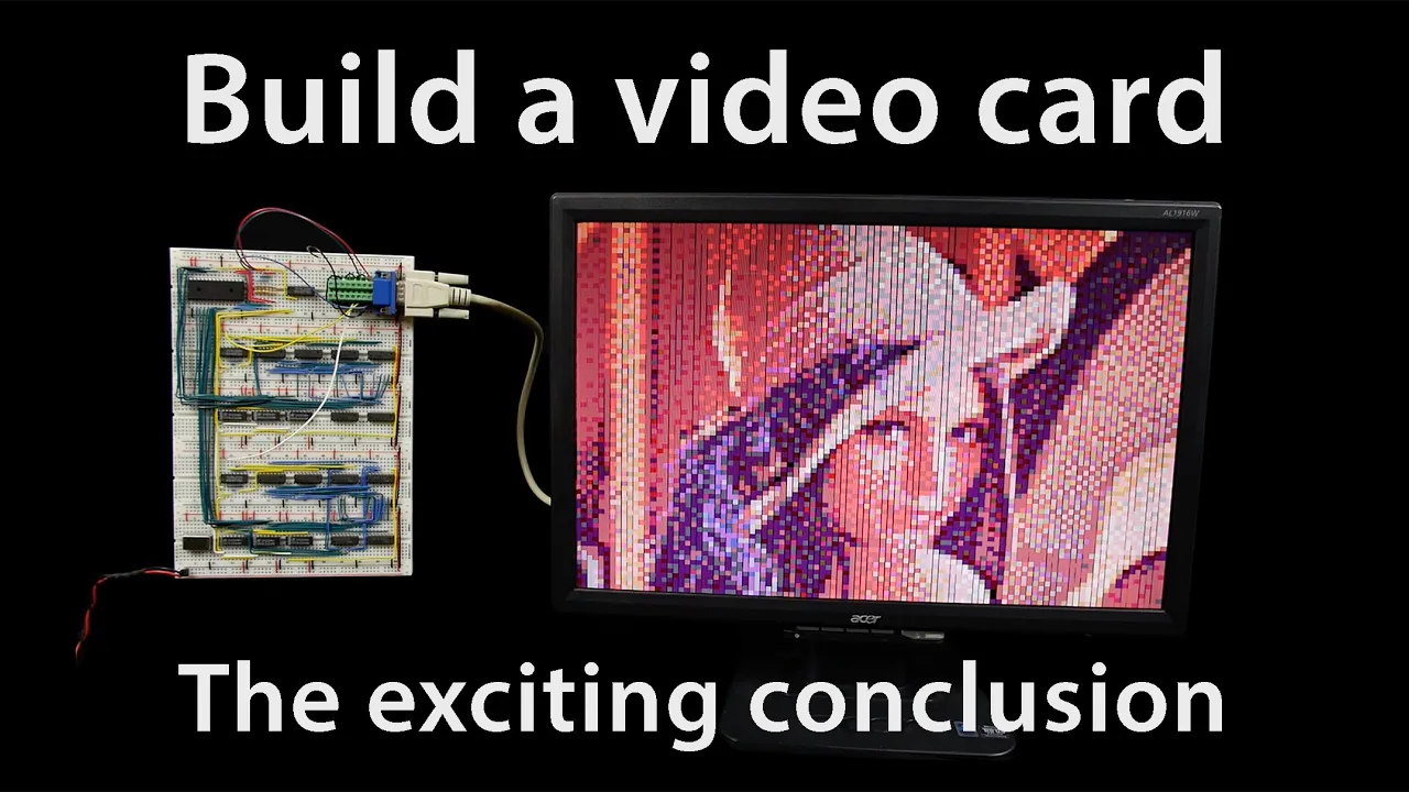
A breadboard video card successfully drives an analog VGA monitor using an EEPROM and a six-resistor DAC, though 150-nanosecond memory access delays produce visible artifacts during rapid scan transitions.
AI-assisted summary of World's worst video card? The exciting conclusion — original source. Check the original for full context.
Source published:
Key ideas
- Ben Eater completes a breadboard VGA video card by driving an AT28C256 EEPROM directly from horizontal and vertical timing counters to look up pixel data. (2:41)
- A simple 2-bit passive resistor digital-to-analog converter per channel drops 5 V TTL logic down to standard 0.7 V VGA levels, generating a 64-color palette using 1.5 kΩ and 680 Ω resistors. (9:37)
- Address line routing constraints and pixel aspect ratio corrections reduce the usable display image to a native 100×75 resolution padded inside a 32 KB binary. (4:44)
- Vertical black artifacts appear on the rendered image because the 150 ns access latency of the AT28C256-15 EEPROM spans up to six 25 ns monitor pixel intervals during address transitions. (22:12)
Detailed notes
## Background Published by Ben Eater on YouTube on July 13, 2019, this video serves as the conclusion to his two-part series on constructing a discrete breadboard video card. According to the description, the project focuses on how VGA uses analog RGB signals, employing an AT28C256 EEPROM to store graphic data and a simple passive digital-to-analog converter to display an image on a standard monitor.
## TL;DR Building upon the VGA sync pulse generator created in part one, Ben Eater routes binary counter lines into an AT28C256 parallel EEPROM configured for a scaled 100×75 image resolution. He designs a 2-bit resistor ladder digital-to-analog converter for each color channel using 1.5 kΩ and 680 Ω resistors against the monitor's 75 Ω load, generating 64 distinct RGB colors alongside NAND-based blanking interval protection. Eater formats a photograph using Photoshop and a custom Python script to pad scanlines into a 32 KB raw binary file, flashes the memory chip, and successfully renders the image onto a VGA screen while analyzing minor timing artifacts caused by the EEPROM's 150 ns access delay.
## Atmosphere & style The presentation maintains Ben Eater's signature calm, methodical, and accessible instructional tone, transforming complex digital logic and circuit design into clear, step-by-step physical demonstrations. Eater speaks with relaxed modesty and understated humor, unbothered by hardware constraints and candidly acknowledging the low resolution and minor visual glitches inherent to a breadboard setup. The viewing experience feels like sitting alongside an expert bench technician, capturing the quiet satisfaction of incremental troubleshooting as inverted gate logic, Python padding errors, and memory latencies are diagnosed and resolved.
## Bulletin - [02:41](https://www.youtube.com/watch?v=uqY3FMuMuRo&t=161s) Ben Eater completes a breadboard VGA video card by driving an AT28C256 EEPROM directly from horizontal and vertical timing counters to look up pixel data. - [09:37](https://www.youtube.com/watch?v=uqY3FMuMuRo&t=577s) A simple 2-bit passive resistor digital-to-analog converter per channel drops 5 V TTL logic down to standard 0.7 V VGA levels, generating a 64-color palette using 1.5 kΩ and 680 Ω resistors. - [04:44](https://www.youtube.com/watch?v=uqY3FMuMuRo&t=284s) Address line routing constraints and pixel aspect ratio corrections reduce the usable display image to a native 100×75 resolution padded inside a 32 KB binary. - [22:12](https://www.youtube.com/watch?v=uqY3FMuMuRo&t=1332s) Vertical black artifacts appear on the rendered image because the 150 ns access latency of the AT28C256-15 EEPROM spans up to six 25 ns monitor pixel intervals during address transitions.
## Key takeaways - [00:00](https://www.youtube.com/watch?v=uqY3FMuMuRo&t=0s) Synchronized horizontal and vertical binary counters track the exact raster coordinates currently being scanned by the monitor. - [01:15](https://www.youtube.com/watch?v=uqY3FMuMuRo&t=75s) Tapping counter bits directly through current-limiting resistors into RGB pins creates basic colored bars, confirming hardware synchronization. - [02:41](https://www.youtube.com/watch?v=uqY3FMuMuRo&t=161s) The AT28C256 parallel EEPROM provides 32 KB of static storage, mapped by counter addresses to output an 8-bit color byte per pixel. - [02:59](https://www.youtube.com/watch?v=uqY3FMuMuRo&t=179s) Because the circuit runs on a 10 MHz clock instead of standard 40 MHz, pixels are quadrupled in width, requiring vertical line doubling and address bit dropping to maintain proper aspect ratio. - [04:44](https://www.youtube.com/watch?v=uqY3FMuMuRo&t=284s) Hardware address constraints leave 7 bits for X and 7 bits for Y, limiting the display image to a 100×75 pixel canvas. - [05:51](https://www.youtube.com/watch?v=uqY3FMuMuRo&t=351s) VGA color inputs require analog voltages between 0.0 V and 0.7 V into an internal 75-ohm monitor termination load. - [06:55](https://www.youtube.com/watch?v=uqY3FMuMuRo&t=415s) Calculating series resistance using a voltage divider with the monitor's 75-ohm internal load determines the resistor values needed for intermediate brightness steps. - [09:37](https://www.youtube.com/watch?v=uqY3FMuMuRo&t=577s) A 2-bit resistor DAC combining 1.5 kΩ and 680 Ω resistors produces four discrete voltage levels (0 V, ~0.23 V, ~0.47 V, ~0.70 V) per color channel, yielding 64 possible colors. - [12:22](https://www.youtube.com/watch?v=uqY3FMuMuRo&t=742s) Asserting color signals during horizontal and vertical blanking intervals can corrupt sync detection or potentially damage CRT monitors. - [13:46](https://www.youtube.com/watch?v=uqY3FMuMuRo&t=826s) A NAND gate fed by display interval flip-flops controls the active-low Output Enable (/OE) pin of the EEPROM to suppress output during blanking intervals. - [18:03](https://www.youtube.com/watch?v=uqY3FMuMuRo&t=1083s) Because 7 horizontal address bits span 128 bytes, each 100-pixel scanline in memory must be padded with 28 zero bytes to keep line addressing aligned. - [20:43](https://www.youtube.com/watch?v=uqY3FMuMuRo&t=1243s) Flashing software requires the binary image to fully match the EEPROM's 32,768-byte capacity, necessitating zero-padding across all unused vertical scanlines up to line 255. - [22:12](https://www.youtube.com/watch?v=uqY3FMuMuRo&t=1332s) The AT28C256-15's 150 ns propagation delay lags behind the monitor's 25 ns pixel sampling rate, causing transient black vertical lines during address transitions. - [23:22](https://www.youtube.com/watch?v=uqY3FMuMuRo&t=1402s) Commercial graphics adapters avoid latency artifacts and support real-time rendering by using fast video RAM rather than EEPROMs.
## Detailed walkthrough ### [00:00](https://www.youtube.com/watch?v=uqY3FMuMuRo&t=0s) Generating RGB Signals and Testing Counter Taps
Ben Eater recaps the foundation established in his previous video, where he designed a breadboard circuit capable of producing a compliant VGA signal. When plugged into a display, the monitor correctly identified the incoming feed as an 800×600 mode signal because the circuit generated precise horizontal and vertical synchronization pulses: a 3.2 µs horizontal sync pulse roughly 38,000 times per second, and a 0.1056 ms vertical sync pulse 60 times per second. This was accomplished using binary counters clocked at exactly 10 MHz. The horizontal counter cycles repeatedly from 0 to 264 counts to define line timing, while the vertical counter tracks scanlines from 0 to 628.
To move beyond blank synchronization and actually render an image, the circuit must drive the VGA interface's red, green, and blue (RGB) analog lines. Because the counters are locked in lockstep with the monitor's raster scan, they track the exact coordinates currently being painted from left to right (0 to 200 counts horizontally) and top to bottom (0 to 600 lines vertically). As Eater puts it: “In other words: because we're synchronized, we can use our counters to know exactly what pixel the monitor is painting at the moment.”
```mermaid flowchart LR accTitle: VGA Timing and Direct Counter Output accDescr: Diagram showing how horizontal and vertical counters synchronize with the monitor and directly drive color lines through resistors. subgraph Counters ["Timing Counters"] HC["10 MHz Horizontal Counter<br/>(0 to 264 counts)"] VC["Vertical Counter<br/>(0 to 628 scanlines)"] end subgraph MonitorPaint ["VGA Beam / Screen"] SYNC["H-Sync & V-Sync<br/>(800x600 Mode Sync)"] RGB["Analog RGB Lines<br/>(0 to 0.7 V)"] end HC -->|"H-Sync Pulses"| SYNC VC -->|"V-Sync Pulses"| SYNC VC -.->|"Bit 4 (16s place)"| R1["Resistor"] -->|"Green signal"| RGB VC -.->|"Bit 3 (8s place)"| R2["Resistor"] -->|"Red signal"| RGB ```
To demonstrate this coordination on the physical breadboard, Eater taps individual output bits directly from the vertical counter and routes them through current-limiting resistors into the color pins: - Connecting the 16s place bit (bit 4) to the green line causes the signal to toggle every 16 scanlines, producing thick horizontal green bands across the display. - Adding the 8s place bit (bit 3) to the red input generates alternating red and green bars alongside yellow stripes where the two colors overlap. - Bringing the blue input into the counter mix yields 16 distinct colored horizontal stripes across the display.
---
[02:41](https://www.youtube.com/watch?v=uqY3FMuMuRo&t=161s) Storing Image Data and Resolving Resolution Constraints
While colorful stripes confirm the timing works, rendering an arbitrary picture requires a dedicated memory buffer. In standard computers, video data resides in system RAM or dedicated VRAM so software can modify pixel values on the fly. For this standalone breadboard build, Eater opts to store a static graphic in an AT28C256 parallel EEPROM, which provides 32 KB of storage. Driving the EEPROM's address pins with the counter outputs allows the memory to look up and output an 8-bit color byte for every distinct X/Y screen coordinate.
Using the EEPROM introduces severe geometric and hardware addressing constraints: - **Pixel aspect ratio:** Because the circuit runs on a 10 MHz pixel clock rather than standard 40 MHz, the visible horizontal area contains 200 wide pixels across 600 vertical scanlines instead of 800×600. Every pixel is naturally four times wider than normal. - **Counter truncation:** To prevent the image from looking vertically stretched, each vertical line must be repeated four times to match the horizontal stretch. Dropping the lowest two bits of a binary counter divides its output count rate by four (0, 0, 0, 0, 1, 1, 1, 1, etc.). - **Address line limitations:** The AT28C256 EEPROM has only 15 address lines ($2^{15} = 32{,}768$ bytes). Storing raw coordinates directly would require more address lines than the chip possesses. Eater resolves this by discarding three bits from the vertical counter (Y) and one bit from the horizontal counter (X).
This reduction forces a compromise on resolution, prompting Eater's candid assessment: “So given what we've got with this EEPROM and to keep the right proportions end up having to drop three bits from our Y counter and one bit from the X counter and that leaves us with a final image resolution of 100 pixels by 75 pixels which you know, I don't know it's maybe not the most impressive resolution but I mean, what do you want for me? I'm trying to build a video card on bread boards.”
---
[05:04](https://www.youtube.com/watch?v=uqY3FMuMuRo&t=304s) Wiring the AT28C256 EEPROM to Counter Addresses
Eater places an additional breadboard adjacent to the counter logic and installs the AT28C256 EEPROM, hooking up $V_{CC}$ (+5 V) and ground. To keep the memory chip permanently configured for continuous reading, he wires the control pins directly to supply rails: - **Write Enable ($\overline{\text{WE}}$):** Tied high (+5 V) to prevent unintended write operations, since write enable is active-low. - **Output Enable ($\overline{\text{OE}}$) and Chip Enable ($\overline{\text{CE}}$):** Tied directly to ground (low) so the EEPROM's output bus remains constantly active and driving data.
He connects 14 address lines between the counters and the EEPROM to supply the X and Y raster coordinates: - **Horizontal (X) address lines:** Seven address lines are wired to the horizontal counter, omitting the least significant bit (bit 0) to scale the width down to 100 pixels. - **Vertical (Y) address lines:** Seven address lines are wired to the vertical counter, skipping the lowest three bits (bits 0, 1, and 2) to scale the height down to 75 lines. - **Unused address pin:** The 15th address line on the EEPROM is tied to ground.
With 7 bits for X and 7 bits for Y, the memory receives a unique 14-bit address for each pixel cell within the 100×75 matrix, outputting an 8-bit data byte on its D0–D7 data pins for every point on the screen.
```mermaid flowchart TD accTitle: Counter to EEPROM Addressing Scheme accDescr: Block diagram illustrating the address line routing from horizontal and vertical counters into the EEPROM to produce an 8-bit color byte. subgraph Counters ["VGA Pixel Counters"] HC["Horizontal Counter<br/>(Skip bit 0)"] VC["Vertical Counter<br/>(Skip bits 0, 1, 2)"] end subgraph Memory ["AT28C256 EEPROM"] A_X["Address A0–A6<br/>(7 bits for X: 100 pixels)"] A_Y["Address A7–A13<br/>(7 bits for Y: 75 lines)"] A14["Address A14<br/>(Tied to GND)"] DATA["Data Outputs D0–D7<br/>(8-bit Pixel Color Byte)"] end HC --> A_X VC --> A_Y A_X --> DATA A_Y --> DATA A14 --> DATA ```
---
[05:51](https://www.youtube.com/watch?v=uqY3FMuMuRo&t=351s) Converting 5 V Digital Logic to Analog 0.7 V VGA Signals
Standard VGA video inputs expect an analog voltage between 0.0 V (completely dark) and 0.7 V (maximum brightness) for each color channel. The EEPROM outputs standard digital CMOS/TTL logic levels (0 V for logic low and 5 V for logic high). Because this requires converting a higher voltage down to a maximum of 0.7 V, a voltage divider is the natural solution.
```mermaid flowchart TD accTitle: Passive Resistor Voltage Divider with Monitor Load accDescr: Schematic flow of the digital output passing through an inline series resistor into the internal 75 ohm load of the monitor. subgraph BreadboardDAC ["Video Card / Breadboard"] V_IN["Digital Output Pin<br/>(5 V High / 0 V Low)"] R_SERIES["Series Resistor (R)<br/>Calculated: ~460.7 Ω"] end subgraph MonitorLoad ["VGA Display Input"] V_OUT["Analog RGB Pin<br/>Target: 0.7 V Peak"] R_INT["Internal Load Resistance<br/>R2 = 75 Ω"] GND["Chassis Ground<br/>0 V"] end V_IN --> R_SERIES R_SERIES --> V_OUT V_OUT --> R_INT R_INT --> GND ```
A standard voltage divider equation determines output voltage based on the resistor ratio: $$\text{V}_{\text{out}} = \text{V}_{\text{in}} \times \frac{R_2}{R_1 + R_2}$$
The VGA specification dictates that monitor inputs feature a 75-ohm input impedance ($R_2 = 75\ \Omega$), which acts as an internal load tied to ground inside the display: - To find the series resistor ($R$) required to step 5 V down to full-scale 0.7 V: $$\frac{75}{R + 75} \times 5 = 0.7$$ - Solving the algebra: $$375 = 0.7R + 52.5$$ $$322.5 = 0.7R$$ $$R \approx 460.7\ \Omega$$ - Placing a $460.7\ \Omega$ series resistor between a 5 V output and the VGA input pin delivers the required 0.7 V.
To achieve varying brightness levels and rich color palettes rather than simple on/off primary colors, intermediate voltages must be produced between 0 V and 0.7 V. For four evenly spaced brightness steps per channel (zero, one-third, two-thirds, and full brightness): - **Full brightness (0.700 V):** Ideal resistor is $460.7\ \Omega$. - **Two-thirds brightness (~0.467 V):** Ideal resistor is $722.9\ \Omega$; Eater substitutes a commonly available $680\ \Omega$ resistor as a close match. - **One-third brightness (~0.233 V):** Ideal resistor is $1535.4\ \Omega$; Eater substitutes a standard $1.5\ \text{k}\Omega$ ($1500\ \Omega$) resistor. - **Zero brightness (0.000 V):** Formed when the digital pin stays low at 0 V.
[09:37](https://www.youtube.com/watch?v=uqY3FMuMuRo&t=577s) Constructing a 2-Bit Resistor DAC and 64-Color RGB Mapping
Ben Eater details how to turn digital outputs into the required analog VGA voltage levels (ranging from 0 to 0.7 volts) using a simple resistor digital-to-analog converter (DAC). By using two inputs (each driven at either 0V or 5V) per color channel, four distinct voltage states can be formed: 1. When both inputs are at 0V, the output is naturally 0V. 2. When only the input tied to the 1.5 kΩ resistor is high (5V) and the other is at 0V, the output yields approximately 0.23V across the monitor's internal 75Ω termination. 3. When the 1.5 kΩ input is low and the 680Ω resistor input is driven at 5V, the voltage reaches roughly 0.47V. 4. When both inputs are driven high (5V), the two resistors combine in parallel. Calculating their equivalent resistance via the sum of reciprocals formula:
$$\frac{1}{R_p} = \frac{1}{1500} + \frac{1}{680}$$
This yields an equivalent resistance of approximately 468Ω, resulting in an output of around 0.7V.
```mermaid flowchart LR accTitle: Two-bit Resistor DAC accDescr: Schematic showing how two digital inputs feed 1.5k and 680 ohm resistors in parallel to generate an analog voltage into a 75 ohm load.
subgraph Inputs["Digital Inputs (0V / 5V)"] Bit0["Bit 0 (LSB)"] Bit1["Bit 1 (MSB)"] end
subgraph Resistors["Resistor Network"] R1["1.5 kΩ Resistor"] R2["680 Ω Resistor"] end
subgraph OutputNode["Analog Output"] VOut["VGA Pin (0 to 0.7V)"] RTerm["75 Ω Monitor Load"] GND["Ground"] end
Bit0 --> R1 Bit1 --> R2 R1 --> VOut R2 --> VOut VOut --> RTerm RTerm --> GND ```
Replicating this simple 2-bit ladder across each of the three color channels (red, green, and blue) allows six bits of EEPROM data to define four intensity levels per channel. Ben points out: “So with just a couple resistors we can take 2 bits of binary data and convert that into one of 4 different voltage levels from 0 to 0.7 volts and if we do that for red green and blue we can use six bits of data coming out of our EEPROM to get four different shades of red green and blue which combine into 64 different colors”. In the 6-bit color byte, the lowest two bits control blue, the middle two control green, and the highest two control red.
- **Resistor values used:** Three 1.5 kΩ resistors and three 680 Ω resistors (one pair per color channel). - **VGA pin assignments:** Red, green, and blue connect to pins 1, 2, and 3 respectively on the standard 15-pin VGA connector, with sync and grounds connected as established previously.
---
[12:22](https://www.youtube.com/watch?v=uqY3FMuMuRo&t=742s) Wiring the DAC and Solving the Blanking Output Bug
Ben wires the six data outputs of the EEPROM into the resistor networks on the breadboard. Data bits 0 and 1 feed into the 1.5 kΩ and 680 Ω resistors for blue; bits 2 and 3 route through the pair for green; and bits 4 and 5 drive the pair for red. The output ends of each resistor pair are tied together to supply the analog signals to pins 1, 2, and 3 of the 15-pin VGA connector, alongside the horizontal sync, vertical sync, and ground lines.
```mermaid flowchart TD accTitle: EEPROM Blanking Logic accDescr: Block diagram illustrating horizontal and vertical display period signals feeding a NAND gate to control active-low Output Enable on the EEPROM.
HDisp["Horizontal Display Period Active"] VDisp["Vertical Display Period Active"] NAND["NAND Gate"] OE["EEPROM /OE (Output Enable)"]
HDisp --> NAND VDisp --> NAND NAND -->|Active Low during display| OE ```
Upon powering up and reconnecting the monitor, the screen stays dark. The monitor recognizes the sync signals, but shows nothing. Ben notes that the EEPROM installed is completely erased, meaning every memory byte holds all ones (0xFF). All ones should light every channel at maximum voltage and produce a solid white screen.
He realizes that driving full voltage constantly means pixels are being asserted even during horizontal and vertical blanking intervals: “And we really shouldn't be putting out any pixels in this blanking time because well it should be blank and in fact, this is one of those things that might actually damage a CRT monitor and hopefully we won't damage my monitor”.
To prevent this, the EEPROM outputs must be disabled whenever the beam enters a blanking interval: - The circuit already tracks the active horizontal and vertical display intervals via flip-flops. - Because the EEPROM's Output Enable (`/OE`) pin is active-low, Ben adds a NAND gate. When both the horizontal display period and vertical display period signals are high, the NAND output drops low, enabling the EEPROM. - After initially wiring the gate inputs to the wrong polarity outputs, he swaps them to the inverted flip-flop outputs: “And there we go now it actually looks like we're getting looks like a white screen”.
---
[15:27](https://www.youtube.com/watch?v=uqY3FMuMuRo&t=927s) Preparing an Image and Formatting Raw Binary Pixel Data
With the breadboard displaying a pure white field, Ben moves to displaying an actual full-color graphic. He finds a public domain photograph of a colorful bird and imports it into Photoshop to format it for the video card's specific constraints. He resizes and crops the canvas down to the hardware's native resolution of 100×75 pixels.
Next, he switches the color mode to indexed color using a custom 64-color palette matching the resistor DAC's voltage steps. Each index corresponds directly to the hardware's color byte encoding (where index 8 represents a specific shade of green, driven by the middle bits). Ben observes of the coarse 100×75 resolution: “So that is that is the best our wonderful breadboard video card can do so, let's go ahead and save this”.
Exporting to `image.png` introduces headers, chunks, and metadata that the raw EEPROM address lines cannot parse. To extract pure byte data, Ben writes a short Python script using the Pillow (`PIL`) library: - The script loads the image to read its 2D array of indexed color pixels. - It iterates across all 75 scanlines and 100 pixels per line. - It writes each raw byte directly into a binary file named `image.bin`.
Inspecting `image.bin` confirms that all byte values are under `0x40` (64 in decimal), matching the expected 6-bit color range.
However, Ben identifies a memory layout mismatch caused by the video card's address generation architecture. The circuit uses 7 bits for horizontal addressing and 7 bits for vertical addressing. While the display only shows 100 pixels per line, resetting the horizontal counter rolls the lower 7 bits from 99 back to 0, while the vertical counter increments bit 7 (the 128s place).
Therefore, every scanline in the EEPROM must span 128 bytes rather than 100 bytes: “so in the EEPROM really even though we only have a hundred pixels per line on the screen in the EEPROM we want to take up 128 pixels per line”. When he alters the inner loop bound from 100 to 128, Python promptly throws an `IndexError: image index out of range`, because the source image is only 100 pixels wide.
[19:41](https://www.youtube.com/watch?v=uqY3FMuMuRo&t=1181s) Padding the Image Data and Programming the EEPROM
When the Python script attempts to read pixel coordinates beyond the boundaries of the 100-pixel-wide image—such as pixel 100, 101, or 128—it throws an `IndexError`. To resolve this, Ben Eater catches the exception and simply writes a zero byte to the binary file whenever an out-of-bounds pixel is requested. Inspecting the generated output reveals the intended layout: a block of data representing the first 100 pixels of an image line, immediately followed by 28 zero bytes padding the line out to 128 bytes, which matches the 7-bit horizontal address space.
```mermaid flowchart LR accTitle: Binary Image Padding and Flashing Pipeline accDescr: Pipeline showing Python conversion with zero padding, flashing via MiniPro, and loading into the EEPROM. subgraph DataPrep ["Data Preparation (Python)"] direction TB A["100x75 Source Image"] --> B["Pad scanlines to 128 bytes"] B --> C["Pad scanlines 75–255 to 0x00"] C --> D["32,768-Byte (32KB) Binary"] end subgraph Hardware ["EEPROM Programming"] direction TB D --> E["MiniPro Software"] E --> F["Commercial Programmer"] F --> G["AT28C256 EEPROM"] end ```
Rather than using the DIY Arduino-based EEPROM programmer he built in an earlier series, Eater opts for a commercial USB programmer with the open-source `minipro` command-line utility, noting that having the raw file ready makes it significantly faster. However, his initial flashing attempt targeting the AT28C256 32-kilobyte EEPROM fails with an error stating `incorrect file size: 9600`. Because the vertical loop only iterated across 75 scan lines ($75 \times 128 = 9,600$ bytes), the file fell short of the full 32K (32,768 bytes) required by the programmer. Address line $A_{14}$ is tied low, leaving an 8-bit vertical address space ($Y = 0$ to $255$). Eater updates the script loop limit to 256, padding all remaining unused vertical lines with zeros until the file reaches exactly $8000$ hex (32,768 bytes). Re-running `minipro` completes successfully.
- The horizontal line length requires 7 bits ($2^7 = 128$ bytes), requiring 28 zeros of padding after the 100 image pixels. - The vertical resolution uses 8 address bits ($2^8 = 256$ lines), requiring lines 75 through 255 to be padded entirely with zeros. - The targeted EEPROM is the Microchip/Atmel AT28C256, a 256K-bit ($32\text{K} \times 8$) parallel EEPROM.
[22:12](https://www.youtube.com/watch?v=uqY3FMuMuRo&t=1332s) Displaying the Image and Diagnosing Timing Glitches
Eater seats the freshly flashed EEPROM back into the breadboard socket and powers on the display system. The monitor immediately syncs and displays the color image of the bird. Inspecting the output on the screen closely reveals faint, thin black vertical glitches scattered across the graphic. Eater observes that the circuit is functional despite these minor imperfections: “So this is our completed video card, but you know, it's producing an image from the ROM. So I'm going to call that a success.”
```mermaid flowchart LR accTitle: Video Card Address Timing Mismatch accDescr: Diagram illustrating clock timing mismatch causing output delay artifacts. subgraph Timers ["Clock & Scan Timing"] A["10 MHz Master Clock<br/>(100 ns per cycle)"] B["Monitor Scan Expectation<br/>(25 ns per 40 MHz pixel)"] end subgraph ChipDelay ["EEPROM Propagation"] C["AT28C256-15 Address In"] -->|tACC = 150 ns max| D["Output Data Valid"] end subgraph ScreenArtifact ["Display Result"] D --> E["Up to 6 Invalid Pixel Windows"] E --> F["Transient 0x00 Outputs (Black Streaks)"] end ```
The underlying cause of the black streaks traces back to EEPROM access latency. The system clock runs at 10 MHz, ticking every 100 nanoseconds, but the VGA monitor expects standard 800×600 @ 72 Hz timing based on a 40 MHz pixel clock—meaning the display scans through a pixel every 25 nanoseconds. Consulting the AT28C256 datasheet reveals that the specific chip model in use (the `-15` speed grade) has a maximum address-to-output access time ($t_{ACC}$) of 150 nanoseconds. Because the address lines change while the internal decoding circuitry takes up to 150 ns to present stable data at the outputs, the signal can remain invalid across up to six consecutive 25 ns monitor pixel intervals. During these transition periods, floating or unasserted data reads as zero volts, appearing on the monitor as narrow black vertical lines.
- Master circuit clock: 10 MHz (100 ns period). - Monitor pixel expectation: 40 MHz (25 ns period). - EEPROM access time ($t_{ACC}$): 150 ns maximum for the AT28C256-15. - Duration of invalid output: up to 6 monitor pixels ($150\text{ ns} / 25\text{ ns} = 6$).
[23:22](https://www.youtube.com/watch?v=uqY3FMuMuRo&t=1402s) Real Video Cards vs. EEPROM and Project Wrap-up
Eater contrasts this breadboard video generator with production computer graphics adapters. Standard graphics cards utilize high-speed video RAM, such as SDRAM, which is engineered specifically for rapid random-access throughput and low latency to avoid access-time artifacts. Furthermore, an operating system or software routine can freely rewrite the contents of video memory in real time to render animations or update desktop UI elements. On this breadboard card, updating an image requires physically extracting, erasing, reflashing, and reseating the EEPROM chip in the breadboard, an operation that is unavoidably slow even when sped up through video editing.
Eater emphasizes that achieving dynamic rendering was never the core objective of the project: “Really the goal was just to get some kind of image on the screen and I'd say this is a success.” He directs viewers interested in recreating or expanding the project to schematics, component lists, and datasheets hosted on his website. He concludes by thanking his Patreon community, noting that the extensive planning, testing, and production time required to design discrete hardware circuits from scratch would not be possible without continuous viewer support.
## Mentioned Ben Eater, AT28C256, Microchip, Atmel, VGA, Python, Pillow, PIL, Adobe Photoshop, MiniPro, Arduino, Patreon
## Video description For part 1, see this video: https://www.youtube.com/watch?v=l7rce6IQDWs Let's build a circuit that displays an image on a VGA monitor! In part 2, I talk about how VGA uses analog RGB signals to send different color pixels to the monitor. I use an EEPROM to store an image and build a simple digital-to-analog converter to generate the color signals to successfully display an image.
Support these videos on Patreon: https://www.patreon.com/beneater or https://eater.net/support for other ways to support.
------------------
Social media: Website: https://www.eater.net Twitter: https://x.com/beneater Patreon: https://patreon.com/beneater Reddit: https://www.reddit.com/r/beneater
Special thanks to these supporters for making this video possible: Name Alexander Catchpole Beau-James Erion Ben Ben Dyson Ben Kamens Ben Williams Christopher Blackmon Dean Winger Debilu Krastas Dušan Dželebdžić Eric Dynowski Erik Broeders fxshlein Gonzalo Belascuen HaykH Ian Tait Ivan Sorokin JavaXP Jay Binks Jayne Gabriele Jimmy Campbell Jordan Scales Justin Duch Manne Moquist Marcus Classon Mats Fredriksson Michael Burke Michael Garland Miguel Ríos Mirko Rener Nathan Wachholz Nicholas Moresco Nick Wrightsman Onion Sniffer Paul Pluzhnikov Randy True Robert Butler Sachin Chitale Sergey Ten SonOfSofaman Stefan Nesinger Steve Gorman Vladimir Kanazir Örn Arnarson
[Source](https://www.youtube.com/watch?v=uqY3FMuMuRo)