Smart Meter Teardown Exposes Remote Tariff Powers Over Spy Myths
bigclivedotcom
While physical inspection disproves surveillance and radiation conspiracies, the units enable utilities to inflate consumer bills by remotely billing for apparent power and enforcing peak-demand penalties.
AI-assisted summary of Inside a smart meter, and the REAL problem with them. — original source. Check the original for full context.
Source published:
Key ideas
- A teardown of a fly-tipped smart meter reveals a cellular telemetry system running standard 2G/3G/4G radio hardware, debunking persistent public conspiracy theories regarding 5G death rays, surveillance microphones, and chemical dispersal systems. (4:46)
- The meter is equipped with a high-current latching disconnect relay that allows utility providers to remotely cut off a customer's power supply over the air if their account falls into arrears. (6:55)
- The primary consumer risk highlighted is remote software programmability, which allows utilities to switch billing calculations from real power to apparent power (billing for reactive loads) or introduce punitive peak-demand pricing during high-load periods. (11:28)
- Physical anti-tamper measures include carbon-loaded conductive rubber contacts that trigger an alert or 'dying gasp' cellular transmission via onboard storage capacitors if the casing is breached or power is severed. (1:35)
Detailed notes
## Background Published on YouTube by bigclivedotcom on October 26, 2018, this video features a teardown of a smart meter salvaged from a pile of fly-tipped building materials after the named utility company failed to respond to inquiries. According to the description, Clive investigates the unit's internal hardware while addressing rampant conspiracy theories concerning government spy microphones, spy cameras, chemtrails, and 5G radiation, alongside the meter's capacity for peak-demand pricing.
## TL;DR Clive disassembles a smart electricity meter, detailing its modular cellular modem, tamper-detection pads, optical interface, and massive remote disconnect relay. Along the way, he inspects the manganin shunt and mains tapping architecture, systematically debunking paranoid claims about embedded surveillance microphones, cameras, or harmful high-power radio emissions. He concludes that the genuine danger of the technology is financial rather than conspiratorial, stemming from energy suppliers' ability to remotely alter firmware to bill for apparent power and impose punitive peak-demand tariffs.
## Atmosphere & style The presentation is calm, pragmatic, and laced with dry benchtop humor as Clive methodically unscrews and probes the hardware. His steady, analytical demeanor sharply contrasts with and deflates the hyperbolic conspiracy theories he examines, grounding every claim in physical circuit traces and component datasheets. The viewing experience feels like leaning over the shoulder of an experienced electronics technician who effortlessly transitions from wry jokes about technophobia to sharp, cynical critiques of corporate utility billing practices.
## Bulletin - [04:46](https://www.youtube.com/watch?v=G32NYQpvy8Q&t=286s) A teardown of a fly-tipped smart meter reveals a cellular telemetry system running standard 2G/3G/4G radio hardware, debunking persistent public conspiracy theories regarding 5G death rays, surveillance microphones, and chemical dispersal systems. - [06:55](https://www.youtube.com/watch?v=G32NYQpvy8Q&t=415s) The meter is equipped with a high-current latching disconnect relay that allows utility providers to remotely cut off a customer's power supply over the air if their account falls into arrears. - [11:28](https://www.youtube.com/watch?v=G32NYQpvy8Q&t=688s) The primary consumer risk highlighted is remote software programmability, which allows utilities to switch billing calculations from real power to apparent power (billing for reactive loads) or introduce punitive peak-demand pricing during high-load periods. - [01:35](https://www.youtube.com/watch?v=G32NYQpvy8Q&t=95s) Physical anti-tamper measures include carbon-loaded conductive rubber contacts that trigger an alert or 'dying gasp' cellular transmission via onboard storage capacitors if the casing is breached or power is severed.
## Key takeaways - [00:00](https://www.youtube.com/watch?v=G32NYQpvy8Q&t=0s) The smart meter features standard heavy brass terminal blocks with a shared neutral path, rather than isolated paths to monitor line and neutral current discrepancies. - [00:00](https://www.youtube.com/watch?v=G32NYQpvy8Q&t=0s) An optical infrared communications port on the front panel provides a magnetic interface for on-site technicians to interrogate the meter and alter parameters. - [01:35](https://www.youtube.com/watch?v=G32NYQpvy8Q&t=95s) Anti-tamper protection relies on conductive carbon-loaded rubber pads pressing against gold circuit traces, breaking the circuit and triggering an alert if the housing or modem is removed. - [01:35](https://www.youtube.com/watch?v=G32NYQpvy8Q&t=95s) The removable modem module utilizes large cylindrical capacitors to store enough residual charge for a 'dying gasp' message when mains power is severed. - [04:46](https://www.youtube.com/watch?v=G32NYQpvy8Q&t=286s) The wireless module operates on standard commercial cellular standards with intermittent packet transmissions, exposing occupants to RF levels equivalent to an ordinary mobile phone. - [06:55](https://www.youtube.com/watch?v=G32NYQpvy8Q&t=415s) The meter contains a massive internal latching relay that remains normally closed without continuous power draw, energizing only when commanded to remotely disconnect service. - [06:55](https://www.youtube.com/watch?v=G32NYQpvy8Q&t=415s) An internal Hall effect sensor is positioned adjacent to the disconnect relay to detect external neodymium magnets placed to defeat or jam the mechanism. - [06:55](https://www.youtube.com/watch?v=G32NYQpvy8Q&t=415s) Optocouplers form an isolation barrier between the mains-referenced measurement circuitry and the low-voltage serial data lines connected to the communications modem. - [09:07](https://www.youtube.com/watch?v=G32NYQpvy8Q&t=547s) Current measurement is conducted across an electronically welded manganin alloy shunt integrated directly into the live busbar path. - [09:07](https://www.youtube.com/watch?v=G32NYQpvy8Q&t=547s) A metal oxide varistor provides transient overvoltage clamping between phase and neutral, though Clive questions the absence of visible series thermal cutoffs in case of degradation. - [11:28](https://www.youtube.com/watch?v=G32NYQpvy8Q&t=688s) Unlike electromechanical Ferraris-disc meters that inherently measure real power, smart meters can be remotely configured to bill for apparent power (volts multiplied by amps), penalizing consumers for reactive loads. - [11:28](https://www.youtube.com/watch?v=G32NYQpvy8Q&t=688s) Remote network programmability enables energy providers to dynamically implement peak-demand pricing spikes during typical evening household usage hours. - [11:28](https://www.youtube.com/watch?v=G32NYQpvy8Q&t=688s) The rollout relies on traditional meter readers being trained to install smart meters, effectively automating away their own long-term employment. - [13:56](https://www.youtube.com/watch?v=G32NYQpvy8Q&t=836s) Internal logic and cellular power are tapped on the incoming mains side before the disconnect relay, ensuring communications remain active even when customer power is remotely severed.
## Detailed walkthrough ### [00:00](https://www.youtube.com/watch?v=G32NYQpvy8Q&t=0s) Provenance and External Features
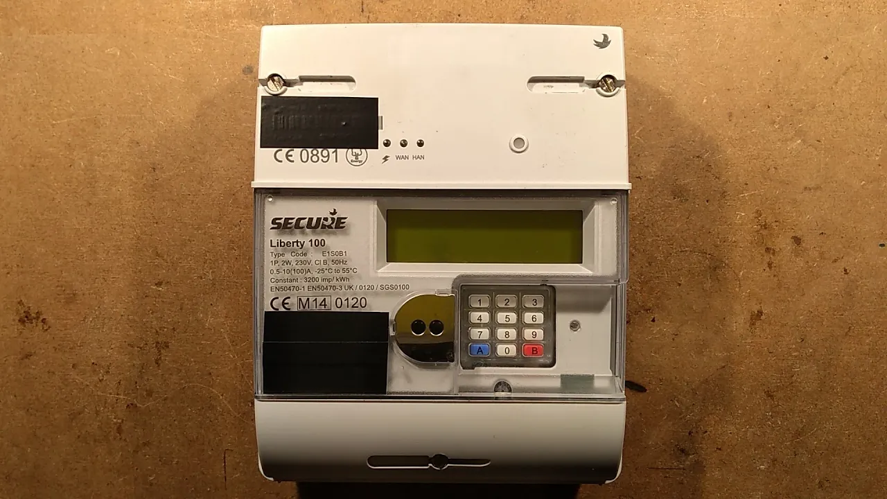
The teardown begins with an explanation of how the smart meter was acquired. Viewers Andy and Lucas were out walking when they stumbled across a fly-tipped pile of builder's rubble and rubbish containing a couple of discarded meters. Because a utility company's name was clearly printed on the unit, they reached out to offer them back, asking if the company was aware they had been dumped. When the company failed to respond, they forwarded the meters to Clive, which he notes “was the correct thing to do.” Clive takes care to cover the external serial numbers with tape to protect everyone involved, admitting that this is actually the second take of the video because he dismantled the meter earlier only to uncover another hidden serial number inside.
Inspecting the meter's exterior reveals standard security and electrical arrangements. The lower terminal cover unclips, revealing holes meant for a tamper-evident sealing wire and crimp. Behind the cover sit four heavy brass terminals arranged as live in, common neutral in the middle, and live out. Clive expresses surprise at finding a shared neutral block rather than isolated neutral paths, remarking: “The common neutral bit surprises me I thought they might actually monitor live and neutral current flow independently to detect if people are trying to bypass a meter in somewhere.” The front housing features a push-button keypad, likely provided for prepayment customers who fall behind on their electricity bills and need to enter numeric top-up codes to restore credit. In addition, an optical infrared communication port ringed by a magnetic collar is present on the front fascia, allowing utility meter readers to slap on an optical probe to interrogate the unit and alter system parameters.
```mermaid flowchart TD accTitle: Smart Meter Functional Architecture accDescr: Diagram illustrating the mains power path, metering components, and isolated communications modem.
subgraph MainsPath["Mains Power Path"] LIN["Live In"] --> RELAY["High-Current Disconnect Relay"] RELAY --> SHUNT["Current Sense Shunt"] SHUNT --> LOUT["Live Out"] NEUT["Common Neutral"] end
subgraph MeterCore["Main Meter Board"] PSU["Low-Voltage Power Supply"] HALL["Hall Effect Magnetic Sensor"] BATT["3.6V Primary Lithium Cell"] OPTO["Opto-Isolators"] IR["Infrared Optical Port"] KEY["Prepayment Keypad"] end
subgraph ModemModem["Cellular Modem Module"] HDR["10-Pin Data Header"] ARM["ARM Microcontroller"] SIM["Manx Telecom SIM Card"] CAPS["Dying Gasp Capacitors"] ANT["PCB Trace Antenna / Ext Port"] end
MainsPath --> PSU PSU --> MeterCore MeterCore <--> OPTO OPTO <--> HDR HDR <--> ModemModem ```
[01:35](https://www.youtube.com/watch?v=G32NYQpvy8Q&t=95s) The Wireless Modem and Anti-Tamper Mechanisms
Dismantling the upper bay exposes the detachable wireless communications modem module that provides the meter's smart functionality. Removing the cover reveals a deliberate physical security system: carbon-loaded conductive rubber pads built into the outer casing press directly down against exposed, gold-flashed contacts on the circuit board below. Clive demonstrates that pulling either the outer lid or the module off breaks this continuous circuit, which triggers an internal anti-tamper flag or immediately radios home to alert the utility company that unauthorized access has occurred. Beside the module header sits a 10-pin interface connector handling low-voltage power and bidirectional serial communications between the meter core and the radio hardware.
Prying open the carrier module reveals a standard, plain white SIM card. Clive wagers that the connectivity is powered by Manx Telecom, noting that regardless of where one is in the world, the Isle of Man provider has historically served as a massive roaming data backbone for mobile and telemetry applications due to its early pioneer status in telecommunications. The module also features an auxiliary SMA-style antenna jack cutout through the side of the case for rural installations where indoor cellular reception is poor. Internally, the modem board hosts an ARM processor, a cellular modem baseband chip, an auxiliary wireless chip possibly intended for short-range Bluetooth or in-home display pairing, and an etched PCB trace antenna. Dominating the board are two massive cylindrical capacitors, which Clive suspects are reserve storage components:
> “Some modems have the facility that if they lose power they will use the residual charge of capacitor to just send a little logging off cord or an error code maybe that is an anti tamper device if you were to suddenly unplug us it holds enough charge on these big capacitors to actually send a message saying and tamper detected...”
- Tamper detection relies on flexible, carbon-loaded rubber bridging blocks resting against gold-plated circuit pads. - The cellular radio board incorporates its own dedicated ARM processing core and an etched, rugged circuit-board trace antenna. - The unit accepts an optional external cellular antenna lead for properties located in signal dead zones. - Dual storage capacitors provide "dying gasp" energy reserves so the modem can transmit a final distress signal if mains power is severed.
[04:46](https://www.youtube.com/watch?v=G32NYQpvy8Q&t=286s) Conspiracy Theories vs. Cellular Reality
Clive pauses the disassembly to confront the wide range of bizarre public panics and online conspiracy theories surrounding the rollout of smart meters. He takes aim at pervasive claims that smart meters bathe households in dangerous 5G death rays, cause cancer, harbor clandestine microphones to eavesdrop on homeowners' private conversations, or secretly disperse mood-altering chemical aerosols into living spaces. He compares these fears to recurring historical technophobia, arguing: “It's the blue light from the streetlights and it's all Gatos just any random thing the attention seekers jump on it and their claim it's bad.”
Addressing the electromagnetic reality, he points out that the radio module inside the meter is nothing more exotic than standard 2G, 3G, or 4G cellular hardware identical to an everyday mobile telephone. Rather than continuously beaming high-power radiation into the home, the meter merely checks into the mobile cell tower at scheduled intervals to exchange packet data or send updated consumption readings. He points out that leaving a mobile phone sitting on an ordinary living room table exposes an occupant to the exact same transmission strengths as the meter mounted away inside an external service box or under the stairs.
[06:55](https://www.youtube.com/watch?v=G32NYQpvy8Q&t=415s) Main Board Disassembly and High-Voltage Switchgear
Removing the front casing and peeling back the rubber keypad membranes brings the high-voltage main board into view. Dominating the lower half of the assembly are heavy brass terminal lugs accompanied by a massive internal power latching relay. This heavy-duty contactor allows the electricity supplier to remotely sever a consumer's power supply over the air if an account falls into arrears. Clive clips a multimeter in diode/continuity test mode across the relay contacts to establish its default resting state. As anticipated, the switch is normally closed, establishing that the meter draws no continuous holding current while the customer is connected and only pulses the solenoid when commanding a disconnect.
Nestled immediately beside the relay mechanism stands an upright semiconductor that Clive identifies as a Hall effect magnetic sensor. This component serves as an anti-fraud measure, detecting whether a consumer has placed an ultra-strong neodymium magnet against the plastic meter enclosure in an attempt to magnetically stall the disconnect relay or distort the measurement circuitry. The main board also hosts a self-contained low-voltage switch-mode power supply and an optical isolation barrier. Optocouplers sit across the division separating the mains-referenced circuitry from the low-voltage communication lines feeding the modem module, protecting the radio hardware from high-voltage transients while facilitating two-way serial data transmission. Soldered directly to the board is a 3.6-volt primary lithium cell designed to maintain clock memory and internal logging during an outage; probing the cell reveals an active reading of 3.65 volts, showing it remains in prime condition.
> “I would expect that maybe normally closed and only powered when they want to disconnect you because that would take the load off it it is it's normally bridging through and it's only when they power that but it's going to disconnect you that makes sense.”
[09:07](https://www.youtube.com/watch?v=G32NYQpvy8Q&t=547s) Current Shunt, Transient Protection, and RF Sensing
Clive examines the heavy-current busbar path leading through the meter to understand how electricity consumption is sampled. Rather than using an inductive current transformer (CT) coil or measuring along the raw copper busbar, the phase conductor features a dedicated slug of specialized metal—likely manganin—electronically welded directly into the line. This precision shunt provides a calibrated, temperature-stable resistance over a compact physical span, across which sensitive metering chips can monitor voltage drop to calculate instantaneous current. Clive notes that concentrating the resistance into this small welded segment must generate some localized heat under heavy continuous loads.
Turning to the surge suppression circuitry, Clive spots a massive Metal Oxide Varistor (MOV) wired directly between incoming phase and neutral to clamp overvoltage spikes. However, he observes a concerning absence of series thermal cutoffs or fuses nearby, raising doubts about fire safety should the varistor degrade from repeated surges:
> “So does that mean that if this metal oxide varistor is to gradually feel over time if that's what it is it would actually potentially get quite hot in there without anything to cut out not sure that seems a bit odd...”
He scans the layout for any RF sniffer tracks or dedicated radio-frequency jammer detection coils designed to flag attempts to disrupt the meter's communications using handheld transmitters, but finds only a few unused surface test pads. The construction appears to be a robust double-sided or multi-layer printed circuit board using dedicated metering application-specific integrated circuits situated alongside the primary shunt.
- Current measurement is handled by a welded low-resistance shunt alloy slug spliced into the primary live busbar. - Transient surge protection relies on a heavy-duty MOV bridging line and neutral, though lacking obvious thermal disconnect protection. - The main PCB uses either multi-layer or dense double-sided routing with dedicated current-sensing logic adjacent to the power rail.
[11:28](https://www.youtube.com/watch?v=G32NYQpvy8Q&t=688s) Internal Electronics and the Real Threat of Smart Tariffs
Examining the printed circuit board, Clive points out components marked as Hall effect sensors optimized for current sensing, along with a resistor network used for voltage sensing to correlate with that current. Looking over the board, he observes a large shield over what appears to be a standard switch-mode power supply, noting wryly that there is no spy microphone to be seen: “I'm not seeing a microphone in here that will please the conspiracy theorists or maybe it wouldn't please the conspiracy theorists.”
```mermaid flowchart TD accTitle: Smart Meter vs Traditional Meter Measurement Capabilities accDescr: Flowchart contrasting how mechanical meters measure real power versus how smart meters can be programmed to measure apparent power or enforce time-of-use tariffs.
subgraph Mech["Traditional Mechanical Meter"] M1["Rotating Ferraris Disc"] --> M2["Measures V x I Phase Relationship"] M2 --> M3["Bills for Real Power (Watts)"] end
subgraph Smart["Remotely Programmed Smart Meter"] S1["Voltage & Current Sensors"] --> S2{"Remote Firmware / Tariff Mode"} S2 -->|"Apparent Power Mode"| S3["Raw V x I (VA) — Ignores Phase Angle"] S2 -->|"Peak Demand Mode"| S4["Time-of-Use Rate Hikes (e.g., Dinner Time)"] end ```
Clive turns to what he considers the genuine, frustrating issue with the rollout: the high degree of remote control suppliers have over these units. Traditional Ferraris-wheel electromechanical meters are inherently accurate at measuring real power because their spinning disc naturally accounts for the phase relationship between voltage and current. Smart meters, however, can be commanded over the network to alter their measurement methodology. Specifically, they can be configured to ignore power factor entirely, calculating apparent power instead by taking the raw current and simply multiplying it by the line voltage.
Beyond billing for reactive loads, remote programmability allows energy companies to manipulate dynamic tariffs. Clive warns that customers will be lured into switching with promises of initial cost savings, only for suppliers to leverage small print that permits unilateral metering changes. During periods of high wholesale electricity prices, suppliers can penalize consumers through peak demand pricing: “...they could introduce peak demand so when they're paying a lot more for the electricity they penalize you directly by saying if you use too much power round about the time you're cooking tea this unit will charge you twice as much during that period of time...”
Finally, Clive laments the social cost of the technology on the utility workforce. Traditional meter readers are being "upskilled" by large outsourcing firms to install these new digital devices: “...they're basically being taught how to install the meter that's replacing their job and once all the meters have been installed what they're going to do are they're gonna lay them off...”
- **Core Sensing Components:** Hall effect current sensors and a dedicated precision resistor divider network for mains voltage measurement. - **Power Calculation Abuse:** Ability to switch remotely from real power ($W$) to apparent power ($VA$), charging domestic customers for inductive or capacitive reactive power. - **Dynamic Pricing Risks:** Remote activation of punitive time-of-use or peak-demand multipliers during typical evening cooking hours. - **Labor Impact:** Manual meter readers are trained to install the very hardware engineered to automate them out of employment.
---
[13:56](https://www.youtube.com/watch?v=G32NYQpvy8Q&t=836s) Circuit Topology and Debunking Conspiracy Theories
Tracing the remainder of the meter's internal architecture, Clive notes that the device is heavily integrated and functional even if the wireless communications module is disconnected. Underneath the shielding sits a substantial microprocessor handling the calculations. The meter incorporates a primary mains disconnect relay, filtering stages, and basic anti-tamper switches.
Inspecting the passive components around the input circuitry, he spots an apparent Class-Y capacitor, which seems unusual given that the unit lacks an earth connection, suggesting it may be coupling high frequencies across to the incoming neutral or phase line for filtering. Tracing the power supply path through a resistor and an inductor, Clive determines that the meter’s internal logic draws its operating power directly from the incoming mains side rather than the metered load terminals. This ensures that opening the internal disconnect relay to cut off a customer's power does not inadvertently kill power to the meter’s own processor and remote communications.
```mermaid flowchart LR accTitle: Internal Mains Tapping and Isolation Architecture accDescr: Schematic flow showing how the internal smart meter logic taps power before the disconnect relay to maintain connectivity when customer power is killed.
Inlet["Incoming Phase & Neutral"] --> PowerTap["Internal Meter PSU"] PowerTap --> Logic["Microprocessor & Cellular Modem"] Inlet --> Relay["Mains Disconnect Relay"] Logic -->|"Remote Trip Command"| Relay Relay --> Terminals["Phase Out to Consumer"] ```
Reflecting on the device's construction, Clive dismisses the sensationalist rumors that circulate around smart meter rollouts. The meter contains no surveillance gear, no optical lenses, and produces no dangerous radiation; the physical anti-tamper mechanisms are actually simpler than anticipated, relying primarily on switch levers rather than complex perimeter wire-trap detection. Assessing the unit overall, he concludes: “It's boring in the sense that it's just heavily integrated and there's not much to see,” closing out the teardown by confirming the meter is simply a well-engineered, robust piece of industrial electronics whose real threat lies in its billing software rather than urban myths.
- **Internal Power Draw:** Tapped ahead of the main isolation relay so the microcontroller and modem stay alive and reachable even if the customer is disconnected remotely. - **Conspiracy Claims Addressed:** - *Harmful Radiation:* None beyond standard cellular modem data transmissions. - *Audio Surveillance:* No microphones present. - *Visual Spying:* No cameras or lenses installed on the boards. - **Tamper Protection:** Relies on straightforward microswitches to flag enclosure opening, without overly elaborate defenses against terminal-probe bypassing.
## Mentioned bigclivedotcom, Manx Telecom, ARM, Alexa, YouTube
## Video description A look at the insides of a modern smart meter with wireless modem. This meter was found amongst a pile of fly-tipped building materials. The company named on it was contacted but failed to respond, so that means we can take it to bits. I've covered the serial number as I usually do with shady things, to avoid the wrath of angry midgets. While I'm inside I also investigate the conspiracy theories about:- Government spy microphones. (Like Alexa for instance.) Chemtrail brain control chemicals. Spy cameras. Brain irradiating 5G death waves. The ability of the meter to be programmed to read apparent power and apply peak demand pricing.
If you enjoy these videos you can help support the channel with a dollar for coffee, cookies and random gadgets for disassembly at:- http://www.bigclive.com/coffee.htm This also keeps the channel independent of YouTube's advertising algorithms allowing it to be a bit more dangerous and naughty.
[Source](https://www.youtube.com/watch?v=G32NYQpvy8Q)