Freight Locomotives Cut Truck Fuel Burn 75% via Inverter-Driven Bogies
Animagraffs
Heavy-haul diesel units beat highway freight efficiency by converting prime-mover output through multi-stage AC power electronics and dynamic motor braking rather than direct mechanical drivetrains.
AI-assisted summary of How a Diesel-Electric Locomotive Works — original source. Check the original for full context.
Source published:
Key ideas
- Diesel-electric locomotives deliver remarkable freight efficiency, moving a 2,000-pound chunk of freight nearly 500 miles on a single gallon of fuel—3 to 4 times more efficient than a semi-trailer truck. (0:00)
- Locomotives do not use direct mechanical transmissions; instead, a 12-cylinder twin-turbocharged prime mover powers an AC alternator, which is rectified to DC and inverted back to variable AC to drive axle-mounted traction motors. (10:12)
- To avoid hazardous antifreeze leaks along rail corridors, locomotives use straight water for cooling and feature automated dump valves that vent all 400 gallons if temperatures drop below 40°F during engine shutdown. (9:06)
- Braking relies on a blended approach pairing pneumatic friction brakes with dynamic electrical braking, which turns traction motors into generators and dissipates massive kinetic energy as heat through rooftop resistor grids. (17:02)
Detailed notes
## Background Published on YouTube by Animagraffs on December 14, 2022, "How a Diesel-Electric Locomotive Works" is an in-depth technical animation created by Jacob O'Neal with research by Wesley O'Neal. According to the description, the video peers deep into the mechanical, electrical, and structural workings of a heavy-haul freight locomotive, rendered entirely in full 3D.
## TL;DR This technical walkthrough details the engineering architecture of modern diesel-electric freight locomotives. It begins with the external hood-unit frame, heavy-duty Type F couplers, and draft gear before examining the 12-cylinder prime mover, compound-sequential turbochargers, and water-cooling systems. It then traces the conversion of diesel power through the main alternator, DC link, and solid-state inverters into axle-hung AC traction motors mounted within articulating trucks. Finally, it outlines the coordinated operation of pneumatic friction and dynamic electric braking alongside the interlocked throttle, reverser, and safety systems inside the operator cab.
## Atmosphere & style The presentation carries a calm, meticulous, and deeply educational tone, driven by pristine 3D animation and Jake O'Neal's measured, analytical narration. The experience feels like examining an intricate technical blueprint brought to life, methodically peeling away layers of steel framing, fluid lines, and electrical conduits to demystify complex systems without manufactured drama or fluff. Paired with subtle, custom ambient music, the walkthrough delivers a hypnotic and deeply satisfying look at the synchronized mechanical brute force of heavy rail transport.
## Bulletin - [00:00](https://www.youtube.com/watch?v=cIQ0yIZgQeE&t=0s) Diesel-electric locomotives deliver remarkable freight efficiency, moving a 2,000-pound chunk of freight nearly 500 miles on a single gallon of fuel—3 to 4 times more efficient than a semi-trailer truck. - [10:12](https://www.youtube.com/watch?v=cIQ0yIZgQeE&t=612s) Locomotives do not use direct mechanical transmissions; instead, a 12-cylinder twin-turbocharged prime mover powers an AC alternator, which is rectified to DC and inverted back to variable AC to drive axle-mounted traction motors. - [09:06](https://www.youtube.com/watch?v=cIQ0yIZgQeE&t=546s) To avoid hazardous antifreeze leaks along rail corridors, locomotives use straight water for cooling and feature automated dump valves that vent all 400 gallons if temperatures drop below 40°F during engine shutdown. - [17:02](https://www.youtube.com/watch?v=cIQ0yIZgQeE&t=1022s) Braking relies on a blended approach pairing pneumatic friction brakes with dynamic electrical braking, which turns traction motors into generators and dissipates massive kinetic energy as heat through rooftop resistor grids.
## Key takeaways - [00:31](https://www.youtube.com/watch?v=cIQ0yIZgQeE&t=31s) Modern freight locomotives adopt a hood unit architecture featuring a narrow central engine housing flanked by walkways to provide visibility in both forward and reverse directions. - [02:38](https://www.youtube.com/watch?v=cIQ0yIZgQeE&t=158s) Heavy-duty Type F couplers utilize interlocking alignment shelves to prevent vertical disengagement during derailments, slotting into elastomeric draft gears that cushion buff and draft collision shocks. - [04:58](https://www.youtube.com/watch?v=cIQ0yIZgQeE&t=298s) Multi-Unit (MU) umbilicals and auxiliary pneumatic hoses synchronize mechanical, throttle, and braking systems across multiple lashed locomotives under the control of the lead cab. - [05:40](https://www.youtube.com/watch?v=cIQ0yIZgQeE&t=340s) The 12-cylinder four-stroke prime mover utilizes computer-managed multi-stage fuel injection—delivering up to eight micro-injections per combustion stroke—to smooth peak pressure and reduce engine knock. - [06:38](https://www.youtube.com/watch?v=cIQ0yIZgQeE&t=398s) Compound-sequential turbocharging combines a smaller high-pressure turbo for instant low-RPM response with a larger low-pressure turbo that feeds compounded boost at higher engine speeds. - [08:31](https://www.youtube.com/watch?v=cIQ0yIZgQeE&t=511s) An Exhaust Gas Recirculation (EGR) loop lowers combustion temperatures to curb nitrogen oxide emissions, deliberately sacrificing some combustion efficiency to satisfy Tier 4 emissions standards. - [12:02](https://www.youtube.com/watch?v=cIQ0yIZgQeE&t=722s) An onboard battery bank enables silent, zero-emissions low-speed maneuvering in maintenance workshops and railyards using the 'JOG' control mode without starting the diesel engine. - [12:22](https://www.youtube.com/watch?v=cIQ0yIZgQeE&t=742s) Three-axle trucks (bogies) employ multi-tier spring and damper suspensions alongside lateral axle float, enabling wheelsets to steer into curves smoothly without climbing the rail head. - [14:30](https://www.youtube.com/watch?v=cIQ0yIZgQeE&t=870s) Pneumatic sanding systems blow silica sand under the wheels during starts and emergency stops below 15 mph to restore adhesion on slick or wet rail surfaces. - [15:27](https://www.youtube.com/watch?v=cIQ0yIZgQeE&t=927s) Electronically Controlled Pneumatic (ECP) systems digitally map each railcar to actuate car brakes sequentially from the rear forward, preventing hazardous train slack run-in. - [17:02](https://www.youtube.com/watch?v=cIQ0yIZgQeE&t=1022s) Dynamic braking reverses stator magnetic fields against rotor momentum, generating electricity that is shunted into ducted resistor grids that glow red hot as they bleed heat into the atmosphere. - [20:13](https://www.youtube.com/watch?v=cIQ0yIZgQeE&t=1213s) Mechanical and electrical interlocks prevent shifting the reverser handle while the throttle is notched above idle or while dynamic braking is engaged. - [20:13](https://www.youtube.com/watch?v=cIQ0yIZgQeE&t=1213s) An automated cab alerter requires periodic physical confirmation from the driver, initiating an emergency brake application if unanswered to guarantee continuous operator alertness.
## Detailed walkthrough ### [00:00](https://www.youtube.com/watch?v=cIQ0yIZgQeE&t=0s) Introduction, Body, and Frame Architecture
Diesel-electric locomotives have served as the backbone of heavy rail transport for more than six decades, delivering unparalleled freight hauling efficiency. As Jake O'Neal emphasizes, “As a measurement of capacity, they can take a 2,000 pound (907 kg) chunk of freight nearly 500 miles (804 km) on 1 gallon (3.8 L) of fuel, which is 3 to 4 times more efficient than a semi-trailer truck.” The physical architecture of modern freight haulers is dominated by the "hood unit" layout, characterized by a slender central engine compartment flanked by exterior walkways. This perimeter walkway setup grants crew members clear visibility in both forward and reverse directions. At the very front sits a full-width "wide cab" or nose portion. Locomotives typically operate with the short hood facing forward, marked by a visible decal letter "F" stamped on the body. For mechanical inspection and emergency service, exterior metal body panels can be unlatched or entirely removed.
The structural envelope breaks down into four sequential zones: the forward nose and operator's cab; the auxiliary (aux) cab crammed with complex control electronics; the central prime mover engine bay; and the rear radiator cab housing cooling apparatus alongside the primary air compressor. The entire superstructure rests on an exceptionally rigid steel or steel-alloy platform termed the underframe. Bolted to the bottom-front of the underframe is the pilot, traditionally known as the cowcatcher, engineered to deflect tracks-level debris that might otherwise derail the consist. Directly above the pilot, a sturdy steel lip called the anti-climber prevents knocked-aside obstacles from riding up and smashing through the cab windows, backed internally by concealed vertical collision posts on either side of the cab structure.
- Distinct identification numbers appear prominently across the front and lateral body panels. - Auditory warning equipment includes rooftop pneumatic air horns and a frame-mounted electronic bell speaker underneath. - A massive manual handbrake wheel is installed near the locomotive’s rear walkway for mechanical securement when parked.
---
[02:38](https://www.youtube.com/watch?v=cIQ0yIZgQeE&t=158s) Coupler Mechanics and Draft Gear
Railcars and locomotives unite through automated mechanical couplers. While trailing freight cars often rely on simpler Type E couplers, heavy-haul locomotives are outfitted with heavy-duty Type F couplers. The Type F design incorporates robust lateral interlocking wings and vertical alignment shelves designed to prevent the coupling heads from disengaging or slipping vertically during derailments or violent run-ins, whereas standard Type E couplers lack these interlocking safety shelves. Couplers connect automatically on contact through opposing knuckle hooks that rotate closed regardless of whether both knuckles enter the collision open or with one open and one closed.
```mermaid flowchart TD accTitle: Coupler Locking and Unlocking Sequence accDescr: Step-by-step mechanical progression of knuckle engagement and manual uncoupling lever action.
subgraph Coupling ["Coupling Engagement"] A["Knuckle collision"] --> B["Knuckle pushes Knuckle Thrower"] B --> C["Lock rides internal channel"] C --> D["Lock drops onto sloped knuckle rear"] end
subgraph Uncoupling ["Manual Uncoupling"] E["Pin Lifter / Cut Lever rotated"] --> F["Lock pulled upward"] F --> G["Knuckle Thrower rotates knuckle open"] end ```
Inside the coupler head, the contour of each knuckle physically slides against the mating coupler's internal geometry to rotate a knuckle thrower, which in turn lifts and frees the internal locking block. As the knuckle swings fully shut, the gravity lock drops along an internal channel and seats against a sloped ramp behind the knuckle heel, securely trapping the mechanism. Uncoupling is executed manually from trackside via a long lever known as the pin lifter or cut lever; rotating this bar draws the lock upward out of engagement, forcing the knuckle thrower to pivot outward and swing the knuckle wide open.
Coupler shanks do not rigidly mount to the locomotive frame; they slot directly into a draft gear assembly that acts as a heavy-duty bidirectional suspension damper. During sudden pushing collisions—referred to as "buff events"—the coupler pushes straight back into the draft gear housing, compressing an internal column of dense elastomeric rubber discs against thick steel stops mounted to the underframe. Conversely, when the locomotive accelerates forward and tugs against its train—termed a "draft event"—an encircling steel yoke pulls the draft gear assembly forward against front stop blocks, compressing the very same rubber disc stack to absorb shock loads before they can crack car frames or snap couplers.
---
[04:58](https://www.youtube.com/watch?v=cIQ0yIZgQeE&t=298s) Trainline Connections and Multi-Unit Synchronization
Interconnecting rolling stock requires more than mechanical latches; an unbroken network of pneumatic and electrical lines runs from the locomotive back across every trailing car. A flexible glad-hand hose distributes pressurized air throughout the train to supply brake reservoirs on individual freight cars, complemented by electrical jumper cables for cars outfitted with electronically controlled pneumatic (ECP) braking support hardware.
When several locomotives are lashed together to pull massive tonnage, an integrated Multi-Unit (MU) cable connector is plugged between them. Jake O'Neal notes that “When multiple locomotives are coupled, the MU or 'multiple unit' connector brings mechanical, engine, and electrical systems under control of the lead locomotive.” When running solo, this bulky umbilical line stows neatly into an unpowered dummy receptacle on the front sill. In addition to the MU data cable, three auxiliary pneumatic hoses link the locomotive consist together to synchronize cab braking controls: - **Main reservoir hose:** Equalizes air storage tanks across all units to power air equipment and charging circuits. - **Actuating hose:** Allows rapid release or override of locomotive independent brakes throughout the lash-up. - **Brake cylinder hose:** Directly communicates braking application pressure to apply or vent the brake shoe actuators simultaneously.
---
[05:40](https://www.youtube.com/watch?v=cIQ0yIZgQeE&t=340s) The Prime Mover and Multi-Stage Injection
The beating heart of the locomotive is its prime mover: a massive 12-cylinder, twin-turbocharged, four-stroke diesel engine. This industrial engine draws its fuel supply from reinforced under-belly fuel cells hung directly beneath the central underframe, capable of carrying up to 5,300 gallons (20,065 liters) of diesel fuel. Because rail accidents can subject undercarriage tanks to severe puncturing impacts, the fuel tank walls feature heavy external plating and internal baffling.
The fuel delivery architecture features separate, high-pressure mechanical pumps designated for each cylinder bank, distributing diesel through multi-walled armored tubing built to endure extreme pressure spikes. Rather than dumping an entire fuel charge into the cylinder in a single blast, modern engine management computers dictate up to eight separate micro-injections per combustion cycle based on real-time feedback from electronic sensors. This multi-stage injection curve softens peak combustion knock, lowers operational engine noise, and significantly improves thermal efficiency across varying engine loads. Nearby auxiliary engine racks support massive lube oil reservoirs, multistage filtration canisters, and replaceable spin-on fuel filters.
---
[06:38](https://www.youtube.com/watch?v=cIQ0yIZgQeE&t=398s) Compound-Sequential Turbocharging and EGR
To maximize volumetric efficiency and burn massive fuel volumes cleanly, the prime mover features two turbochargers set up in a compound-sequential arrangement. Compressing intake air naturally generates intense heat, which expands the gas and decreases its oxygen density; therefore, the pressurized air charge is diverted through a dual-sided charge air cooler (intercooler) to drop its temperature before it reaches the intake manifold.
```mermaid flowchart LR accTitle: Compound Sequential Turbocharger Airflow accDescr: Flow diagram showing low-RPM single-stage turbocharging transitioning to high-pressure compound boosting.
subgraph IntakeAir ["Induction & Cooling"] Air["Ambient Air Intake"] --> LP["Large Low-Pressure Turbo"] LP --> HP["Small High-Pressure Turbo"] HP --> CAC["Dual-Sided Charge Air Cooler"] CAC --> Manifold["Engine Intake Manifold"] end ```
The compound-sequential configuration divides labor according to exhaust energy levels: - **Low RPM operation:** Weak exhaust gas flow easily spools up the smaller, high-pressure turbocharger. Ambient intake air enters an intake port, travels through the idling large turbocharger, and feeds the small turbo's compressor wheel, providing instantaneous boost without severe turbo lag. - **High RPM operation:** As engine speed climbs and exhaust energy intensifies, an exhaust bypass valve opens to blast the turbine wheel of the large, low-pressure turbo. The large turbo now provides primary compression, ramming dense, high-volume air straight into the intake of the smaller turbo, which compresses it further.
To satisfy strict Tier 4 emissions mandates, the exhaust layout incorporates an Exhaust Gas Recirculation (EGR) loop. A diverter valve taps scorching exhaust gas directly off the left cylinder bank, routing it through an onboard liquid EGR cooler before blending it back into the fresh intake airstream. As Jake O'Neal points out regarding this trade-off, “Sending some exhaust gas back through the combustion process lowers combustion efficiency in favor of greatly reducing exhaust pollutants overall,” primarily by dampening peak flame temperatures to inhibit the formation of harmful nitrogen oxides ($NO_x$).
---
[09:06](https://www.youtube.com/watch?v=cIQ0yIZgQeE&t=546s) Water Cooling and Freeze Mitigation Systems
Because glycol-based antifreeze introduces severe chemical disposal costs and hazardous leak liabilities along rail corridors, modern freight locomotives use pure water as their primary cooling medium. The locomotive carries a dedicated water tank holding nearly 400 gallons (1,500 liters), pressurized and circulated through internal circuits via an engine-driven centrifugal water pump.
Cooling takes place inside a rear radiator cab lined with stacked radiator cores and governed by thermostatically regulated external airflow shutters. A rooftop cooling fan draws outside air upward through these radiator banks as hot water circulates through rows of internal finned tubes. This chilled liquid loop services multiple heat-generating systems: - Dissipating heat from the engine block jackets and cylinder heads. - Absorbing thermal energy inside the EGR cooling core. - Cooling the turbocharger bearing housings and casing jackets. - Regulating temperatures inside the primary air brake compressor. - Circulating through an auxiliary fuel pre-heater during freezing weather to prevent paraffin wax drop-out in the diesel supply.
Relying entirely on straight water poses severe mechanical risks during harsh winter shutdowns. To prevent frozen water from cracking engine blocks and rupturing cooling tubes, automatic dump valves monitor system temperatures. Should the locomotive engine shut down and ambient coolant temperatures plunge below 40°F (4.5°C), these spring-loaded mechanical dump valves trip open, purging every gallon of cooling water onto the trackbed.
---
[10:12](https://www.youtube.com/watch?v=cIQ0yIZgQeE&t=612s) Electrical Generation, Power Inversion, and Traction Motors
Locomotives do not employ mechanical transmissions, clutches, or direct drive shafts to turn their wheels. Instead, the diesel prime mover acts solely as a power station, turning the shaft of a massive electrical alternator that produces high-voltage alternating current (AC). Because generating several thousand horsepower produces intense electrical resistance heating, the alternator relies on a dedicated air blower drawing cool outside air via side-mounted intake screens.
```mermaid flowchart LR accTitle: Diesel-Electric Power Conversion Path accDescr: Sequence showing mechanical conversion from diesel power to AC generation, DC rectification, DC link, AC inversion, and traction motors.
subgraph PowerPlant ["Power Generation"] Diesel["Diesel Prime Mover"] --> Alt["Traction Alternator (AC)"] end
subgraph AuxiliaryCab ["Power Electronics (Aux Cab)"] Alt --> Rect["Rectifier Banks (AC to DC)"] Rect --> DCLink["DC Link Smoothing Circuit"] DCLink --> Inv["Variable Inverters (DC to AC)"] end
subgraph RunningGear ["Trucks"] Inv --> TM["Axle-Hung Traction Motors (AC)"] end ```
The generated AC electricity requires elaborate conversion inside the auxiliary cab before it can drive the train: 1. **Rectification:** High-voltage AC power from the main alternator flows into banks of solid-state rectifiers that convert the current into direct current (DC). 2. **DC Link Conditioning:** Jake O'Neal explains the engineering reasoning behind this intermediate stage: “These traction motors require fine-tuned speed control. Without getting into too much detail, it's simply easier to regulate variable motor speed with DC current as opposed to AC. As such, a fairly intricate conversion process takes place from the alternator to the traction motors.” The DC link filters out voltage spikes, stabilizes harmonic distortion, and regulates the common bus. 3. **Inversion:** Modern solid-state inverters convert the smoothed DC current back into variable-frequency, variable-voltage AC power tailored to the exact rotational requirements of the motors.
This three-phase AC electricity feeds six large traction motors hung inside the wheel trucks. Flexible duct assemblies force high-volume blower air into the traction motors to dissipate operational heat. Tucked directly beneath the auxiliary cab sits a bank of heavy-duty storage batteries. In addition to cranking over the prime mover during cold starts, these batteries store enough chemical energy to power the traction motors independently, enabling crews to silently switch and spot the locomotive across short distances in railyards without ever starting the diesel engine.
---
[12:22](https://www.youtube.com/watch?v=cIQ0yIZgQeE&t=742s) Trucks (Bogies) and Wheel Adhesion Mechanics
The massive weight of the underframe rests on two three-axle wheel assemblies termed trucks or bogies. A critical mandate of truck engineering is maintaining adhesion—maximizing the physical contact patch between the steel wheels and the rail head to prevent wheel slip under extreme tractive loads.
```mermaid flowchart TD accTitle: Bogie Suspension and Articulation Components accDescr: Interconnection of primary suspension, secondary dampers, and underframe coupling mechanisms on a locomotive truck.
subgraph PrimarySuspension ["Primary Suspension (Axle to Bogie)"] PSprings["Dual Helical Springs per Axle"] HorizPlay["Axle Lateral Clearance Play"] end
subgraph SecondarySuspension ["Secondary Suspension (Bogie to Frame)"] SideBearers["Rubber-Stack Side Bearers"] RotDamp["Vertical-Axis Yaw Dampers"] VertDamp["Vertical Shock Absorbers"] end
subgraph FrameMounting ["Tractive Connection"] TracPin["Center Traction Pin / Rod"] Hooks["Extreme-Travel Safety Hooks"] end
PrimarySuspension --> SecondarySuspension SecondarySuspension --> FrameMounting ```
Truck flexibility and track compliance rely on a multi-tiered suspension assembly: - **Primary Suspension:** Heavy helical steel coil springs flank both ends of every axle journal box to dampen high-frequency rail irregularities, paired with a set of vertical shock absorbers mounted on one side to damp bogie bouncing. - **Secondary Suspension:** Pairs of yaw dampers suppress rotational hunting around the vertical axis. Heavy-duty flexible side bearers—built from laminated vulcanized rubber discs—are pinned directly to the underframe, allowing the trucks to articulate, tilt, and slide beneath the locomotive chassis. - **Axle Articulation:** Individual axles retain a small degree of lateral float. This internal compliance allows front, middle, and rear wheelsets to self-steer into curved track sections independently without climbing the rail head. - **Traction Pin & Safety Stops:** High-strength center traction rods transmit mechanical pulling forces directly into the locomotive underframe, while forged steel safety lugs encircle the bogie perimeter to limit extreme truck displacement in the event of track washouts or collisions.
Every wheelset features an axle-hung traction motor supported by heavy frame brackets that pivot directly with axle deflection. A bull gear and pinion reduction gearbox transfers rotational torque from the motor output shaft directly to the drive axle.
---
[14:30](https://www.youtube.com/watch?v=cIQ0yIZgQeE&t=870s) Traction Sand Systems and Braking Fundamentals
When steel wheels encounter wet, oily, or icy rails, the coefficient of friction drops dramatically. To restore grip, the trucks feature an automated pneumatic sanding system used primarily during heavy dead-stop starts, emergency braking, or whenever the locomotive travels at speeds below 15 mph (24 km/h). Sand is stored in four large structural sandboxes located at the front and rear corners of the locomotive, accessible via external filler spouts. Pneumatic delivery lines run down to targeted sand nozzles situated ahead of and behind the truck wheels, blowing a high-velocity stream of sharp silica sand directly between the wheel-tread contact patch and the rail surface for travel in either direction.
Harnessing the kinetic energy of an accelerating train weighing tens of thousands of tons presents massive technical hurdles. As Jake O'Neal emphasizes, “The ability to efficiently haul incredible tonnage comes with a serious technical challenge: stopping the train.” Retarding and halting this mass relies on two completely distinct braking architectures: dynamic electrical braking (which converts motor momentum into electrical resistance) and traditional pneumatic air brakes, which mechanically clamp composite friction shoes directly against the rotating steel wheel treads.
[15:27](https://www.youtube.com/watch?v=cIQ0yIZgQeE&t=927s) Pneumatic Brake System and ECP Control
The pneumatic braking setup relies on an onboard air compressor that pressurizes air and stores it inside large side-mounted reservoirs. The brake system draws directly from these tanks to actuate mechanical linkages throughout the trucks (bogies). Air-driven cylinders located at the front and back of each truck drive pushrods and levers connected to the brake shoes. The arrangement varies along the frame: one cylinder handles just a single brake shoe, whereas another cylinder is linked to drive two shoes simultaneously. Despite this linkage variation, each wheel is acted upon by only one brake shoe.
```mermaid flowchart TD accTitle: Train Pneumatic and ECP Braking Architecture accDescr: Flow diagram showing compressed air generation, cab-level electronic control, trainline air pipe distribution, and car-level braking actuation.
subgraph Locomotive ["Lead Locomotive"] COMP["Onboard Air Compressor"] --> RES["Side Air Reservoirs"] ECP_BRAIN["ECP System Brains<br/>(Under Cab)"] RES --> TRUCK_CYL["Truck Brake Cylinders<br/>(Single & Linked Shoes)"] end
subgraph Trainline ["Train Consist Distribution"] RES --> BPIPE["Train Brake Pipe"] ECP_BRAIN -->|"Precision Sequencing Signals"| CAR_CTRL BPIPE -->|"Pneumatic Supply"| CAR_RES["Individual Car Air Reservoirs"] end
subgraph Railcars ["Individual Railcars"] CAR_RES --> CAR_CYL["Car Brake Cylinders"] CAR_CTRL["Car Identifying Unit & Controller"] --> CAR_CYL end
subgraph EndOfTrain ["Consist Tail"] EOT["End of Train (EOT) Device"] end
CAR_CTRL -.->|"Identifies Last Car"| EOT ```
Running through the rear of the locomotive is the continuous trainline brake pipe, which delivers compressed air down the entire length of the train to every single railcar. Each individual car carries its own dedicated air reservoir, guaranteeing a local air supply whenever that car requires braking effort.
Modern freight consists integrate Electronically Controlled Pneumatic (ECP) systems to replace pure mechanical-pneumatic latency with rapid digital management. The electronic processing unit (“the brains”) of the ECP system is mounted directly underneath the operator's cab. Every car in the consist is fitted with an identifying controller setup, and an End of Train (EOT) device connects to the final car so the system can verify the full train consist and its sequence. Because every car is mapped and addressed electronically, sophisticated braking maneuvers become possible: “For example, brakes can be applied progressively from the last car in the train forward so cars don't ram into each other.”
[17:02](https://www.youtube.com/watch?v=cIQ0yIZgQeE&t=1022s) Dynamic Braking System
Dynamic braking occurs inside the heavy electric traction motors mounted to the axles. An electric motor consists of a rotor core with a stationary magnetic field surrounded by a dense set of electrical windings called the stator. Under normal motoring conditions, passing current through conductive stator windings creates an electromagnetic field that rotates, which drives the rotor. Because the stator's field is generated electronically, it can be adjusted or reversed to act directly against the rotor's rotation.
```mermaid flowchart LR accTitle: Dynamic Braking Energy Flow accDescr: Illustrates how reversing traction motor magnetic fields generates electricity, which is dissipated as heat through resistor grids or potentially captured in regenerative systems.
subgraph MotorAction ["Traction Motor"] ST["Stator Windings<br/>(Electromagnetism)"] RT["Rotor Spin<br/>(Axle Momentum)"] ST -->|"Magnetic Field Reversed"| RESIST["Mechanical Resistance / Braking"] RESIST --> GEN["Traction Motor Becomes Generator"] end
subgraph EnergyDissipation ["Dynamic Brake Box"] GEN --> GRID["Resistor Grids<br/>(Bleeds Energy as Intense Heat)"] FANS["Ducted Cooling Fans"] -->|"Blows Air Across"| GRID end
subgraph FutureTech ["Alternative / Future Tech"] GEN -.->|"Regenerative Braking"| BATT["Battery Energy Recovery"] end ```
Adding this electromagnetic counter-resistance effectively transforms the traction motors into electrical generators. The generated electricity cannot be thrown back onto the rails; instead, it is diverted up into the dynamic brake box, where massive resistor grids bleed off the energy as intense heat. These resistors sit inside isolated duct channels ventilated by powerful cooling fans, and under heavy braking, they get so hot that they emit a bright red glow.
Dynamic braking brings substantial retarding force with very few additional moving mechanical parts, dramatically cutting down wear and tear on consumable friction brake shoes. This process mirrors regenerative braking seen in passenger electric vehicles, where vehicle momentum is recaptured to recharge battery banks. While future freight locomotives may adopt energy-recovery hardware instead of releasing dynamic braking energy as waste heat, modern operations rely on a blended method: “Locomotives generally use a blended approach with both pneumatic and dynamic systems playing a carefully orchestrated role in stopping the train.”
[19:00](https://www.youtube.com/watch?v=cIQ0yIZgQeE&t=1140s) Nose Section and Sub-Cab Electronics
Access to the nose and operator's cab is gained through an exterior entry door on the front nose. Stepping inside reveals a hallway lined with vital electronic modules and crew accommodations before ascending into the operating deck:
- **Electronics Cabinet**: Contains the Head of Train (HOT) device, which communicates with the End of Train unit at the rear of the consist. - **Event Recorder**: Functions as the train’s data recorder (black box) for telemetry and speed tracking. - **Distributed Power System Radio Module**: Provides wireless remote control links to auxiliary/unmanned locomotives distributed mid-train or at the rear, rather than physically coupled to the lead locomotive. - **Yard Download Radio and GPS**: Enables maintenance crews to download stored event recorder logs wirelessly once in a terminal yard, paired with GPS positioning hardware. - **Crew Amenities**: Directly opposite the electronics bay sits an onboard toilet/bathroom compartment, positioned immediately adjacent to a compact crew refrigerator.
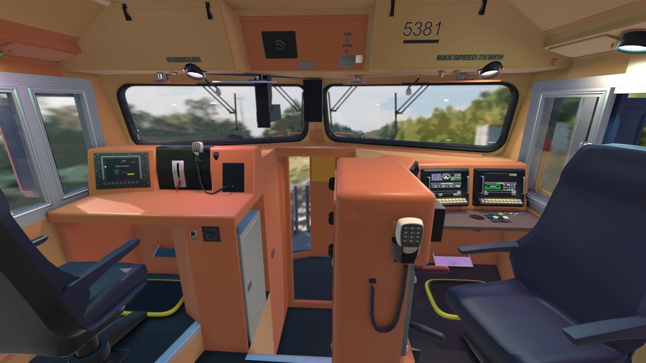
Stairs lead up from the nose entry hallway into the main operator's cab, passing switches that control the internal lighting along the climb. Looking forward from the back of the cabin reveals the operator's console on one side and a secondary crew member's console directly across from it.
[20:13](https://www.youtube.com/watch?v=cIQ0yIZgQeE&t=1213s) Operator Cab Controls and Interlocks
The operator’s workstation features twin smart multi-function displays that provide real-time diagnostic readings and critical system gauges, controlled via rows of tactile pushbuttons lining the bottom of the screens. Safety and operational alerts are clustered nearby:
- **Alerter System**: A prominent alerter button sits beneath the displays to ensure driver alertness. “The alerter system sounds every few minutes or so, depending on locomotive speed. If the alerter button is not pressed within a number of seconds, brakes are automatically applied.” - **Horn and Bell Sequencer**: A horn sequencer button automatically triggers the locomotive horn and bell together at regulated intervals when moving above 0.5 mph (0.8 km/h). Individual horn levers and bell buttons sit nearby for manual sounding. - **Switch Control Panel**: Houses toggles such as the dynamic brake switch. This switch is kept on for the lead unit but remains flipped off when the unit is being remotely controlled as a trailing locomotive, matching standard lead/trail control configurations. The panel also contains the gauge illumination dimmer and a cab call switch to ring an audible alarm bell in trailing locomotive cabs.
```mermaid flowchart TD accTitle: Reverser and Throttle Mechanical Interlocks accDescr: Decision tree illustrating the interlock logic preventing misuse of the reverser handle, throttle lever, and dynamic brakes.
subgraph Interlocks ["Mechanical & Electrical Interlocks"] REV_POS{"Reverser Position?"} REV_POS -->|"Centered (Neutral)"| THROTTLE_LOCK["Throttle Locked in Idle"] REV_POS -->|"Moved to Forward / Reverse"| THROTTLE_FREE["Throttle Lever Unlocked"]
THROTTLE_POS{"Throttle Above Idle?"} THROTTLE_POS -->|"Yes"| REV_LOCK["Reverser Handle Locked in Position"] THROTTLE_POS -->|"Idle"| REV_FREE["Reverser Can Be Shifted"]
DYN_BRAKE{"Dynamic Braking Active?"} DYN_BRAKE -->|"Yes"| REV_LOCKED["Reverser Handle Locked"] DYN_BRAKE -->|"Off"| REV_OK["Reverser Operational"] end ```
Directional control and powertrain regulation use strictly interlocked levers to prevent catastrophic mechanical or electrical failure: - **Reverser Handle**: Dictates directional movement (forward, neutral, reverse) and is completely removed by the operator whenever the locomotive is parked or trailing as a helper unit. - **Throttle Handle**: Governs engine RPM and tractive power delivered to the axles; it functions as the train's gas pedal, where a steady notch setting is ideal for hauling. - **Interlock Logic**: The throttle cannot be advanced past idle if the reverser is centered. If the throttle is notched anywhere above idle, the reverser cannot be moved from its forward or reverse notch. Furthermore, the reverser is firmly locked in position if dynamic braking is actively engaged. - **Brake and Sand Levers**: Features an independent dynamic braking lever, duplicate alerter/horn/bell buttons, sander switches, a two-way cab radio, an automatic train air brake handle for consist-wide air pressure regulation, and an independent brake lever dedicated exclusively to the locomotive’s own shoes. - **Ancillary Controls**: Rotary switches along the lower console govern the cab interior heater and front/rear exterior headlights.
[23:09](https://www.youtube.com/watch?v=cIQ0yIZgQeE&t=1389s) Engine Control Panel and Crew Station
Along the rear wall of the cab, behind the primary driving station, sits a fold-out jump seat underneath circuit breaker arrays and a dedicated, protected engine control panel.
| Engine Switch Position / Control | Function & Operational Details | |:--- |:--- | | **JOG** | Moves the locomotive solely under battery power without starting the diesel engine; used for low-speed maneuvering inside maintenance workshops. | | **START** | Readies circuits so pressing the adjacent **ENGINE START** pushbutton initiates the cranking sequence. | | **ISOLATE** | Leaves the diesel engine idling but fully disconnects the main generator and traction power to the wheels. | | **RUN** | Normal road operation mode for generating traction. | | **MULTIPLE UNIT (MU)** | Configures electrical and pneumatic slave connections across multiple coupled locomotives. | | **AUTO STOP OVERRIDE** | Inhibits automated engine shutdown systems from killing the engine at idle for a duration of two hours. | | **Lighting Switches** | Governs front walkway "ditch" crosswalk lamps, illuminated cab exterior number boards, and interior gauges. |
On the opposite side of the cab rests the dedicated crew member's station, outfitted with an ergonomic observation and training seat. The crew console includes its own smart diagnostic screen on the left, an emergency brake valve dead center to dump brake pipe pressure in a crisis, a horn button, and independent heater controls. Directly above, facing through the windshield, inward-facing and outward-facing safety cameras continuously record cab activity and track conditions for event logging.
## Notable quotes > [14:30](https://www.youtube.com/watch?v=cIQ0yIZgQeE&t=870s) The ability to efficiently haul incredible tonnage comes with a serious technical challenge: stopping the train. — Jake O'Neal
> [06:38](https://www.youtube.com/watch?v=cIQ0yIZgQeE&t=398s) Sending some exhaust gas back through the combustion process lowers combustion efficiency in favor of greatly reducing exhaust pollutants overall — Jake O'Neal
## Mentioned Animagraffs, Jacob O'Neal, Wesley O'Neal, Blender 3D, Soundcloud, Type E coupler, Type F coupler, Electronically Controlled Pneumatic (ECP), Multi-Unit (MU), Exhaust Gas Recirculation (EGR), End of Train (EOT), Head of Train (HOT), Distributed Power System, GPS
## Video description Peer deep into the workings of a heavy-haul freight locomotive, rendered in full 3D!
CREDITS Jacob O'Neal - Modeling, animation, texturing, vfx, music, narrative script Wesley O'Neal - Research, technical script
MUSIC I composed the background music specifically for this video. Hear "Locomotion" on my Soundcloud: https://soundcloud.com/jakeoneal/locomotion
SOFTWARE USED I use Blender 3D to create these models. It's free and open source, and the community is amazing: https://www.blender.org/
0:00 Intro 00:31 Body and frame 02:38 Coupling 04:14 Draft gear 04:58 Coupling cables 05:40 Engine 06:38 Turbocharging 08:31 Exhaust gas recirculation system (EGR) 09:06 Water 10:12 Electrical 10:31 Traction motors 12:02 Batteries 12:22 Trucks / bogies 14:30 Sand system 15:06 Braking 15:21 Pneumatic brake system 17:02 Dynamic braking system 19:00 Nose / Operator's cab 20:13 Operator controls 23:09 Engine control panel 24:06 Crew member's area 24:37 Final tour
Correction: 0:10 Before commenting, check the top pinned "VIDEO CORRECTIONS" thread.
[Source](https://www.youtube.com/watch?v=cIQ0yIZgQeE)