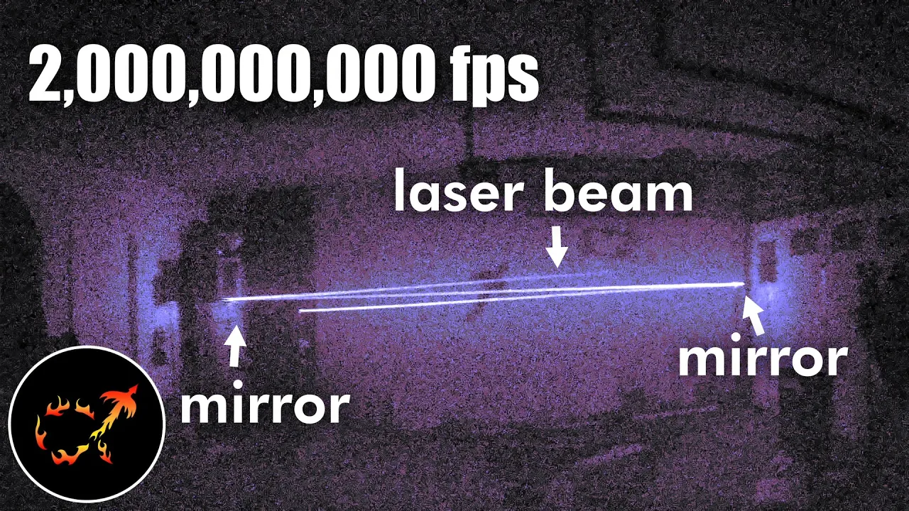
AlphaPhoenix 2B-FPS Camera Shows Geometry Alters Apparent Light Speed
AlphaPhoenix
Apparent light speed fluctuates between near-infinite and halved rates depending on detector position because finite photon return paths compress or stretch arrival times across space.
AlphaPhoenix upgraded his custom high-speed imaging rig to capture HD video at two billion frames per second (0.5 ns intervals) using a single-pixel photomultiplier tube paired with a synchronized two-axis scanning mirror. (0:00)
The setup sidesteps the need for impossible multi-gigahertz full-frame sensors by tiling over 900,000 discrete 1x1 pixel time series generated by synchronized 15-nanosecond laser pulses repeating at 3,000 Hz. (2:29)
Because light's total travel time equals the path to the scatterer plus the path back to the lens, geometric perspective alters apparent velocities: beams directed away from the camera appear to move at half the speed of light, while beams returning toward the camera appear to travel nearly instantaneously. (23:09)
To achieve 2 gigasamples per second on an oscilloscope restricted to single-channel mode, both the PMT sensor measurement and the laser synchronization trigger share a single coaxial line separated in time by a 500-nanosecond physical cable delay line. (20:15)
Detailed notes
## Background
Published by AlphaPhoenix on YouTube on October 17, 2025, the video introduces an upgraded DIY camera capable of recording at two billion frames per second. The channel description notes that after a year of development, the creator uses the rig to investigate a bizarre optical quirk in the apparent speed of light, laying the conceptual groundwork for upcoming experiments in refraction and wave interference.
## TL;DR
AlphaPhoenix constructs an ultra-high-speed camera capable of two billion frames per second by combining a single-pixel photomultiplier tube, a steering gimbal mirror, and precise synchronization via an oscilloscope. Filming a pulsed laser ricocheting between mirrors in a fog-filled garage reveals an apparent paradox: light traveling away from the camera appears to move at half speed, while returning light seems to traverse the room almost instantaneously. This phenomenon is demonstrated to be an observational artifact of finite photon flight times from different points in space, demonstrating how detector geometry slices obliquely through spacetime.
## Atmosphere & style
The presentation is an infectious blend of hands-on garage engineering, playful self-deprecation, and genuine scientific awe. AlphaPhoenix navigates through stripped gears, makeshift coaxial delay lines, and hacky oscilloscope configurations with the scrappy, humorous determination of a maker who thrives on iterative troubleshooting. As the data finally resolves into clean visualizations of traveling photons, the mood transitions from lighthearted workshop tinkering to mind-bending philosophical reflection on the relativistic nature of time and observation.
## Bulletin
- [00:00](https://www.youtube.com/watch?v=o4TdHrMi6do&t=0s) AlphaPhoenix upgraded his custom high-speed imaging rig to capture HD video at two billion frames per second (0.5 ns intervals) using a single-pixel photomultiplier tube paired with a synchronized two-axis scanning mirror.
- [02:29](https://www.youtube.com/watch?v=o4TdHrMi6do&t=149s) The setup sidesteps the need for impossible multi-gigahertz full-frame sensors by tiling over 900,000 discrete 1x1 pixel time series generated by synchronized 15-nanosecond laser pulses repeating at 3,000 Hz.
- [23:09](https://www.youtube.com/watch?v=o4TdHrMi6do&t=1389s) Because light's total travel time equals the path to the scatterer plus the path back to the lens, geometric perspective alters apparent velocities: beams directed away from the camera appear to move at half the speed of light, while beams returning toward the camera appear to travel nearly instantaneously.
- [20:15](https://www.youtube.com/watch?v=o4TdHrMi6do&t=1215s) To achieve 2 gigasamples per second on an oscilloscope restricted to single-channel mode, both the PMT sensor measurement and the laser synchronization trigger share a single coaxial line separated in time by a 500-nanosecond physical cable delay line.
## Key takeaways
- [00:00](https://www.youtube.com/watch?v=o4TdHrMi6do&t=0s) The 2 billion fps camera captures light traveling roughly 6 inches per frame, revealing apparent speed variations when beams bounce between mirrors.
- [02:29](https://www.youtube.com/watch?v=o4TdHrMi6do&t=149s) True real-time full-frame multi-billion fps imaging is cost-prohibitive, requiring a scanning 1x1 pixel sensor architecture that tiles synchronized time series into an HD composite.
- [05:40](https://www.youtube.com/watch?v=o4TdHrMi6do&t=340s) A stationary optical tube pointing up at a two-axis gimbaled mirror prevents mechanical wobble while achieving 720p resolution via a 12-bit magnetic encoder on yaw and a belt reduction drive on pitch.
- [10:32](https://www.youtube.com/watch?v=o4TdHrMi6do&t=632s) A custom 3D-printed magnetic torque limiter protects servo motor gearboxes from high-inertia stops by rapidly dropping holding force when axial push exceeds magnetic attraction.
- [11:43](https://www.youtube.com/watch?v=o4TdHrMi6do&t=703s) The camera's spatial pixel size is governed by a 2 mm pinhole positioned at the focal length of the optical tube, chosen over a sharper 1 mm hole to maximize photon throughput.
- [13:51](https://www.youtube.com/watch?v=o4TdHrMi6do&t=831s) The photomultiplier tube converts single photons into avalanches of roughly one million electrons across dynodes, requiring complete shielding from stray workshop monitor backlights to avoid saturation.
- [16:26](https://www.youtube.com/watch?v=o4TdHrMi6do&t=986s) Physical propagation delays through the lens, vacuum tube, and coaxial cables mean information corresponding to approximately 57 distinct video frames is in transit within the hardware at any given instant.
- [20:15](https://www.youtube.com/watch?v=o4TdHrMi6do&t=1215s) Operating the oscilloscope in single-channel mode at its maximum 2 GS/s rate required multiplexing the PMT signal and laser sync pulse onto one 50-ohm line separated by an unspooled 500 ns coaxial delay cable.
- [23:09](https://www.youtube.com/watch?v=o4TdHrMi6do&t=1389s) Recorded imagery represents an oblique slice through time rather than an instantaneous snapshot, because every frame records photons delayed by both outward laser propagation and return path length to the camera.
- [24:45](https://www.youtube.com/watch?v=o4TdHrMi6do&t=1485s) When light scatters back toward a collocated camera, path-length doubling halves the apparent speed of light, whereas light traveling directly toward an opposing camera appears almost infinite in speed.
- [26:55](https://www.youtube.com/watch?v=o4TdHrMi6do&t=1615s) Filming a laser reflecting from a spinning disco ball demonstrates these relativistic timing delays on a human scale, echoing Ole Rømer's 17th-century astronomical measurements of light speed across Jupiter's moons.
## Detailed walkthrough
### [00:00](https://www.youtube.com/watch?v=o4TdHrMi6do&t=0s) The 2 Billion FPS Camera and the Bouncing Light Paradox
AlphaPhoenix introduces an upgrade to a high-speed camera built the previous year. While the original rig captured video at one billion frames per second, the new version captures footage at two billion frames per second in HD resolution. Constructed from one mirror, one lens, two tubes, assorted cables, a bizarre custom flash bulb, and a few hundred lines of Python code, this setup is fast enough not only to watch light move through space, but literally “fast enough to see the past.”
```mermaid
flowchart LR
accTitle: Laser Ricochet Experiment Setup
accDescr: Diagram showing laser firing across the garage between two parallel mirrors before striking a distant wall.
subgraph GarageSetup["Garage Light Path"]
A["Focused Laser Diode"] -->|"Beam shoots down room"| B["Far Mirror"]
B -->|"Ricochet 1"| C["Parallel Mirror"]
C -->|"Ricochet 2"| D["Far Wall Impact"]
end
```
To demonstrate its capabilities on the most requested viewer experiment, AlphaPhoenix mounts a high-power, carefully focused laser across his garage. The beam shoots toward the far wall into a mirror, bounces back to a parallel mirror, and ricochets back and forth repeatedly before missing the glass and terminating against the wall. A conventional long-exposure photograph shows the continuous beam path just as a human eye would see it. At two billion frames per second, light covers roughly 6 inches (15 cm) per frame, moving strictly at the cosmic speed limit. However, repositioning the camera produces a bizarre optical anomaly: the light moving away from the camera appears to travel far slower, while the light returning back toward the camera appears to travel dramatically faster—almost instantaneously. This apparent contradiction challenges the fundamental principle of the constancy of the speed of light:
> “Light in any reference frame will never move any faster or any slower than this speed. But, what happens if I move the camera?”
[02:29](https://www.youtube.com/watch?v=o4TdHrMi6do&t=149s) How to Cheat a Billion Frames per Second: 1x1 Pixel Tiling
Capturing video at two billion frames per second in true real-time with full spatial arrays is practically impossible:
> “Basically, if you want to record video at a billion frames per second, you pretty much can't. Not at any reasonable resolution, with any reasonably accessible consumer technology, for any remotely reasonable price, which is why setups like this kind of cheat.”
Viewers on previous videos assumed the footage relied on stroboscopic time-lapses (discrete sequential still frames), but the setup actually records full high-speed video at the specified frame rate—at a spatial resolution of exactly one pixel ($1\times1$). Every single pulse of the laser generates a one-pixel time series. To construct a two-dimensional image, a gimballed mirror sweeps the field of view across thousands of discrete pointing angles. Because the laser pulses are precisely synchronized with the sensor's sampling, these hundreds of thousands of individual pixel timelines can be tiled together side-by-side:
```mermaid
flowchart TD
accTitle: Single-Pixel Tiling Process
accDescr: Explains how a single pixel time-series is repeatedly captured at different mirror angles and compiled into an HD image.
subgraph Capture["Data Acquisition"]
P["Laser Pulse (15 ns)"] --> S["High-Speed 1x1 Sensor"]
M["Gimbal Mirror"] -->|"Steps to angle (x,y)"| S
S -->|"1D time trace (2 Gfps)"| D["Data Buffer"]
end
subgraph Reconstruction["Post-Processing"]
D --> T["Tile >900,000 Synchronized Traces"]
T --> F["Final HD Video (1280x720 at 2 Gfps)"]
end
```
The resulting composite produces the exact perspective that would be captured by a monolithic sensor containing over 900,000 ultra-fast elements firing simultaneously during a single-shot event, without the exorbitant industrial cost.
[05:40](https://www.youtube.com/watch?v=o4TdHrMi6do&t=340s) Rebuilding the Mirror Gimbal and Motion Control
Because the detector assembly is heavy and sensitive, the camera sensor remains stationary pointing directly up at the ceiling. The optical view is steered around the room using a two-axis gimbal mirror mounted above it. Because every unique direction the mirror targets becomes an individual pixel in the rendered frame, pointing accuracy and repeatability dictate image quality. The original version relied on hobby servos direct-driving both axes on a flexible 1/4"-20 threaded rod mount, making it prone to drift, wobble, and mechanical failure.
To reach 720p HD resolution ($1280 \times 720$), the mirror requires high angular precision:
- **Yaw (Horizontal Axis):** A servo equipped with a 12-bit magnetic encoder divides a full $360^\circ$ circle into 4,096 discrete positions. Direct-driving the yaw axis through a $112^\circ$ arc yields 1,280 unique positions—providing a wide field of view comparable to a standard wide-angle lens.
- **Pitch (Vertical Axis):** The pitch axis faces a geometric hurdle: tilting a mirror by $5^\circ$ rotates the reflected beam by $10^\circ$ due to reflection across the surface normal, cutting angular resolution in half. To resolve this, AlphaPhoenix implemented a timing belt and pulley reduction drive, converting larger motor rotations into fine, stiff angular steps after literature confirmed the positional repeatability of belt drives.
The scan sweeps in horizontal lines while the laser blinks roughly 3,000 times per second with pulses lasting only 15 nanoseconds each. The laser is unlit for $99.99\%$ of the duty cycle, but during its brief bursts it shines roughly 7,000 times brighter than it appears to the naked eye.
During development, aggressive rapid decelerations caused the high-inertia gimbal assembly to strip the tiny plastic gears within the servo motors:
> “Turns out that when you get the whole swivel assembly swiveling, and then the motor tries to lay on the brakes, the big swivel assembly keeps on swiveling.”
AlphaPhoenix resolved this by programming on-board velocity and acceleration ramps and adjusting PID parameters, using LLM-assisted code to prevent violent stops. However, unsatisfied with relying solely on software limits to protect delicate gearboxes, he sought a low-range mechanical torque limiter.
[10:32](https://www.youtube.com/watch?v=o4TdHrMi6do&t=632s) The Magnetic Torque Limiter
To safeguard the delicate motor driving the mirror assembly against physical crashes, AlphaPhoenix devised a custom magnetic mechanical fuse. The design had been lingering in his head for about a day and a half before he put it together: two shafts connected by interlocking teeth held in contact with magnets rather than conventional springs. Using magnets provides a distinct mechanical advantage over springs: springs grow stiffer and resist more as they are stretched, whereas magnets drop off in attractive force as the distance increases, allowing the mechanism to unstick rapidly and cleanly once a threshold torque is reached.
The mechanism was assembled from six 3D-printed parts, four magnets, and glue. Although it theoretically could have been condensed into just two printed pieces, he separated the design to avoid layer lines binding against each other during sideways motion. The teeth panels were printed sideways to keep their contact surfaces smooth, while the hub was printed flat to ensure the flexible arms remained strong. In operation, if excessive torque is applied to the shaft, the angled teeth push against one another, generating an outward axial force. The moment that force exceeds the magnetic attraction holding the assembly closed, the teeth disengage, the unit pops open, and the motor shaft spins harmlessly without shredding its internal gearing.
- The magnetic torque limiter serves as a mechanical fuse preventing motor gear failure during mechanical carriage crashes.
- Magnets yield a rapid release curve compared to springs, which progressively stiffen under tension.
- The 3D print orientation was carefully chosen: teeth printed sideways for low-friction surface interaction, hubs printed flat for structural flexibility and tensile strength.
[11:43](https://www.youtube.com/watch?v=o4TdHrMi6do&t=703s) The Optics Train: Lens, Focal Length, and Pinhole
AlphaPhoenix jokes that referring to the optical assembly as an "optics train" is overly dramatic, considering it consists merely of a single lens and a single pinhole. Light reflected downward by the scanning mirror passes into this vertical optical tube. Although he equated the pinhole to a camera aperture in a previous build, he clarifies that this analogy is only strictly true for out-of-focus light; because the pinhole sits directly at the lens's intended focal length, it functionally determines the spatial pixel size of the camera.
He laser-cut several pinholes in black cardboard, calculating that a 1 mm diameter was theoretically optimal for the camera's intended angular resolution. However, he deliberately opted for a 2 mm aperture instead. As he explains: “I ended up going with the bigger 2 mm one because I'm a glutton for data and I was willing to accept slightly fuzzier images as long as I could cram four times as many photons through that hole.”
Focusing the system involves a straightforward analog calibration. The lens resides inside a threaded 3D-printed column that screws up and down to adjust distance relative to the sensor plane, secured in place with a locking ring. To align focus, the user illuminates the target scene brightly, opens the column's access doors, and places a slip of white paper at the pinhole plane. Once the projected image appears sharp on the paper, the lens position is locked. By isolating a tiny patch of this focused image through the pinhole, the setup samples light arriving from only one specific spatial angle while blocking the surrounding scene, ensuring that each measurement corresponds to an isolated pixel.
[13:51](https://www.youtube.com/watch?v=o4TdHrMi6do&t=831s) The Photomultiplier Tube and Oscilloscope
At the base of the optical column sits the light detector: a photomultiplier tube (PMT). Vacuum tube PMTs are staggeringly sensitive instruments capable of registering single-photon absorption events. During early testing, AlphaPhoenix suspected his PMT was defective and had already opened an online order page to replace it after struggling through hours of noise and poor signal. The culprit turned out to be ambient light leakage: even with the sensor sealed inside opaque black plastic housings, the faint backlight bleed from "black" computer monitors across the workshop was flooding the tube. He recalled that during his previous year's setup, he had to seal off every window, mask every tiny indicator LED with tape, and operate exclusively in total darkness at night to avoid swamping the sensor.
Once shielded from stray background photons, individual light hits generate electrical currents that pass across a 50-ohm load resistor, transforming current into a measurable voltage fed directly into a high-speed digital oscilloscope. This newly acquired oscilloscope measures electrical potential differences between its probe and ground clip at an astonishing rate of two billion samples per second (2 GSa/s), digitizing the voltage trace into onboard RAM every 0.5 nanoseconds. When triggered by a sharp signal threshold, the scope freezes recording and presents a continuous trace of voltage over time, representing light intensity across discrete half-nanosecond intervals.
```mermaid
flowchart TD
accTitle: Photon Detection Signal Chain
accDescr: Flow diagram tracing the arrival of a photon through the optics to digital sampling in the oscilloscope.
subgraph Optics ["Optical Path"]
P["Photon enters lens"] --> PH["2 mm Pinhole (Pixel Selector)"]
end
subgraph Sensor ["Photomultiplier Tube (PMT)"]
PH --> PC["Photocathode releases electron"]
PC -->|"~22 ns cascade"| DY["Dynodes multiply to ~1,000,000 e⁻"]
end
subgraph Processing ["Electronics & Digitization"]
DY --> COAX["Coaxial Cable (~5-6 ns delay)"]
COAX --> R50["50 Ω Resistor (Current to Voltage)"]
R50 --> SCOPE["Oscilloscope (Sampled every 0.5 ns / 2 GSa/s)"]
end
```
[16:26](https://www.youtube.com/watch?v=o4TdHrMi6do&t=986s) The Pipeline of Traveling Information
AlphaPhoenix breaks down the staggering physical time delays required for information to propagate through the entire detection chain, tracking an idealized photon moving through space at approximately one foot per nanosecond (the speed of light, $c$). After a laser pulse leaves the emitter, it scatters off an airborne fog droplet and travels into the scanning mirror, angling downward through the focusing lens. From the lens to the PMT photocathode face spans roughly 60 millimeters, meaning light spends about four full video frames (at 0.5 ns per frame) simply traveling inside the camera chassis before impact.
Upon striking the photocathode metal, the photon ejects a single electron via the photoelectric effect. This primary electron accelerates through an internal cascade of dynodes within the vacuum envelope, multiplying into an avalanche packet of roughly one million electrons over a transit time of approximately 22 nanoseconds. When this packet empties into the output coaxial cable, it initiates an electron displacement wave that travels toward the oscilloscope slightly below the speed of light, introducing an estimated cable delay of 5 to 6 nanoseconds.
Because information moves at finite physical speeds, an enormous amount of analog history is buffered inside the system concurrently. As he observes: “If we're recording a video with this camera and we just saw recorded the fact that the laser turned on and we call that frame zero, the light entering the camera lens at that moment contains information about frame number 58. Information about 57 frames of video are moving through this camera at once.” If one could freeze time along the length of the signal cable, physical pockets of electron compression—"scrunching"—would correspond directly to distinct successive frames of ultra-high-speed footage propagating at the speed of electricity.
[19:40](https://www.youtube.com/watch?v=o4TdHrMi6do&t=1180s) The Need for Synchronization
Because the single-pixel PMT can record only one spatial coordinate at a time, assembling a coherent two-dimensional video requires scanning the mirror across an entire field of view and stitching together hundreds of discrete $1 \times 1$ pixel time-series captures. If each trace started arbitrarily, jitter between shots would cause horizontal image tearing, where portions of the frame would appear lagged or completely desynchronized. To ensure every recorded pixel trace shares an identical temporal baseline registered precisely to the firing of the laser pulse, the system depends on a rigid synchronization or triggering pulse routed into a secondary channel on the oscilloscope.
[20:15](https://www.youtube.com/watch?v=o4TdHrMi6do&t=1215s) Single-Channel Oscilloscope Hack and Cable Delays
To achieve an effective two billion frames per second without investing in a prohibitively expensive laboratory-grade instrument, AlphaPhoenix was forced to trigger the oscilloscope and collect measurement data simultaneously on a single channel. As he wryly warns, “Electrical engineers in the audience may want to avert their eyes AT THIS TIME.” The oscilloscope only achieves its maximum sampling rate of 2 gigasamples per second when operating in single-channel mode—a constraint he had not realized prior to purchasing the device. Rather than simply routing the photomultiplier tube (PMT) signal into the scope and terminating it with an internal 50-ohm resistor, he terminated the signal path into an external 50-ohm cable routed across the room back toward the laser. The PMT signal shoots past the scope's high-impedance tap down into the extended cable while the scope samples it on the fly.
```mermaid
flowchart LR
accTitle: Oscilloscope Single Channel Multiplexing Architecture
accDescr: Diagram illustrating how the PMT sensor signal and laser trigger pulse share a single coax line without interfering.
subgraph SENSORS["Signal Generation"]
PMT["PMT Sensor"]
LASER["Laser Feedback Board"]
end
subgraph SCOPE_LINE["50-Ohm Transmission Path"]
SCOPE["Oscilloscope Tap<br/>(2 GS/s, Single Channel)"]
SPOOL["500 ns Coax Delay Line<br/>(Unspooled Spool)"]
end
PMT -->|"PMT Pulse (Immediate)"| SCOPE
SCOPE -->|"Wasted PMT Energy"| SPOOL
LASER -->|"Inverted Trigger Pulse"| SPOOL
SPOOL -->|"Delayed Trigger Pulse"| SCOPE
```
At the exact moment the laser fires, a laser feedback current is picked up, directed to a second board where it is inverted and amplified, and then dispatched through hundreds of feet of coaxial cable back toward the scope. This creates bidirectional propagation through the long line: the PMT signal travels down the cable away from the scope, while the synchronization trigger travels back toward it. The timing is tuned so the oscilloscope first logs the high-speed optical brightness data from the PMT, and hundreds of nanoseconds later, receives the inverted trigger pulse used to align frames across successive laser pulses. Placing the synchronization signal far away in time guarantees it cannot couple electrical noise into the critical optical measurement.
- Terminating both ends with 50-ohm resistors (with high-impedance probing at the scope) caused signal attenuation, but eliminated back-and-forth reflections.
- Instead of building a complex active delay circuit, a 500-nanosecond spool of coaxial cable was purchased and left rolled up on the floor to generate the required physical propagation delay.
- The fundamental theory behind this setup grew out of an earlier video series on electricity waves and impedance matching that AlphaPhoenix created for his secondary channel.
[23:09](https://www.youtube.com/watch?v=o4TdHrMi6do&t=1389s) Seeing the Past and the Geometry of Light Propagation
Examining the recorded data brings immediate satisfaction: “I love it when the data shows you exactly what you want to see. Doesn't always happen.” In physical reality, every sensor and human eye only ever observes the past; looking at a computer screen involves perceiving photons emitted a few nanoseconds prior. However, standard photography never reveals light propagation because exposure times are vastly too long. Even an exposure as short as 1/4000th of a second captures photons originating immediately adjacent to the lens in the exact same frame as photons emitted 50 miles away, completely smearing out any time delay across an average.
```mermaid
flowchart TD
accTitle: Path Length Delay Effects on Apparent Light Speed
accDescr: Comparison of perceived light propagation speed depending on camera position relative to the laser source.
subgraph FORWARD["Forward Scattering (Camera Behind Laser)"]
direction LR
L1["Laser Source"] -->|"Path A: Outward"| S1["Scatterer (Fog)"]
S1 -->|"Path B: Return"| C1["Camera (Collocated)"]
NOTE1["Total Path = 2x Distance<br/>Apparent Speed = c / 2"]
end
subgraph RETURNING["Backscatter / Opposed Geometry"]
direction LR
L2["Laser Source"] -->|"Increasing Distance"| S2["Scatterer (Fog)"]
S2 -->|"Decreasing Distance"| C2["Camera (Opposite End)"]
NOTE2["Total Path = Constant<br/>Apparent Speed = Infinite / Instant"]
end
```
Because the ultra-high-speed camera samples discrete nanosecond windows, external spatial geometry dictates the observed arrival time. When light scatters off fog particles suspended in the air, the camera detects a delayed pulse governed by two combined distances: the path from the laser to the scatterer, and the path from the scatterer to the camera sensor. If the scattering points are equidistant from the lens, differences in photon arrival time purely depict the true forward motion of the wavefront. However, when the camera is positioned next to or behind the laser source, photons scattering from points farther down the room must travel both out to the target and all the way back to the sensor. This effectively doubles the total distance traveled between successive scattering sites, creating an optical illusion where the speed of light appears halved.
- As AlphaPhoenix frames the conceptual shift: “The image formed by this camera is not an objective view of the world at a single moment in time, but a perspective taking a slice obliquely through time.”
- When the laser beam travels directly toward the camera—or when the camera sits at the far end of the garage facing the source—increasing distance from the laser is offset by decreasing distance to the camera, making the beam appear to cross the entire room almost instantaneously.
- Arranging mirrors to bounce the beam back and forth creates alternating passes within a single composite frame, juxtaposing apparent superluminal speeds with dramatic slowdowns.
[26:55](https://www.youtube.com/watch?v=o4TdHrMi6do&t=1615s) Relativistic Artifacts, the Disco Ball, and Ole Rømer's Legacy
AlphaPhoenix emphasizes that these apparent velocity changes do not mean the physical speed of light is varying or anisotropic. Rather, these artifacts are the inevitable consequence of probing space with detectors that rely on signals traveling at a finite velocity: “We will never know exactly what the world looks like everywhere at the same instant in time. In fact, that whole question is sort of assuming that the same instant in time exists everywhere in the world and that doesn't even work.”
This relativistic delay effect appears vividly when filming a laser reflecting off a spinning disco ball in a room filled with fog:
- The divergent light rays scattering off fog droplets close to the camera as they stream outward appear on the sensor almost instantaneously.
- The corresponding bright dots where those same rays hit the garage wall behind the disco ball materialize only after a measurable, conspicuous delay, because the wall is physically farther away from the camera's optical receiver.
The underlying principle directly mirrors the historical method used by Ole Rømer in the 1670s to perform the first quantitative measurement of light speed by tracking timing discrepancies in the eclipses of Jupiter’s moon Io as Earth moved closer to and farther from the planet. While Rømer worked across interplanetary distances, AlphaPhoenix reflects on how striking it is to see the exact same physical law play out across ordinary human objects in an everyday garage, setting the stage for future experiments in refraction and optical interference.
## Notable quotes
> [26:55](https://www.youtube.com/watch?v=o4TdHrMi6do&t=1615s) We will never know exactly what the world looks like everywhere at the same instant in time. In fact, that whole question is sort of assuming that the same instant in time exists everywhere in the world and that doesn't even work. — AlphaPhoenix
## Mentioned
AlphaPhoenix, Ole Rømer, Python, Jupiter, Io
## Video description
I've upgraded! It took almost a year, but today I finally get to show off a TWO billion frame per second camera! I really want to record refraction, interference, and other awesome stuff with this camera, but today I'm looking into a really strange quirk of the speed of light. In a way, understanding this weird phenomenon is kind of a prerequisite for everything else I want to do with this camera - I hope you find it as interesting as I have!
MANY more technical details for the curious:
https://www.youtube.com/playlist?list=PLAYHMTkuzdT3Zwk3UialNtxXrpkmaC_ZI
bonus points to hakonjdjohnsen for advice on colormaps, R520 for a typo, and @dl33 for the top suggestion in last video's comments!
Massive thanks to my top Patreon supporters!
birdiesnbritts
John Sosa Trustham
Vladimir Shklovsky
Aloysius Sparglepartz
Jason Whatley
Lohann Paterno Coutinho Ferreira
nothings
Eugene Pakhomov
Glenn Willen
R520
Nick F
Mirko Rener
Chris Connett
Tyler Filla
Chandler Freeman
Benjamin Manns
MPG
Seth Reuter
Danny Thomas
Lucy Fur
tiaz
David Antoš
Chris Duvarney
Nick Wage
John T
Jack Serrino
Ethan Sifferman
Dit55
Ashley Hauck
Scott Schlesier
Steve
James K
Allan Adams
Usama
Cody and Sara
Doug Strain
Justin McCaskill
Chapters:
0:00 Bouncing light is actually complicated!
5:35 The mirror
11:50 The optics train
13:51 The sensor
19:40 The cables?
23:02 Seeing the past
Media Credits:
I Dunno by grapes is licensed under a Creative Commons Attribution license
http://ccmixter.org/files/grapes/16626
Arcadia - Wonders by Kevin MacLeod is licensed under a Creative Commons Attribution 4.0 license. https://creativecommons.org/licenses/by/4.0/
Switched on Carcassi by Brian Bolger, YouTube Music license
Future Freeway by Adam MacDougall
Disco Knights by Quincas Moreira
This Close by half.cool
Gemini by half.cool
Mountain by Text Me Records / Bobby Renz
Local Elevator by Kevin MacLeod is licensed under a Creative Commons Attribution 4.0 license. https://creativecommons.org/licenses/by/4.0/
Meme from The Spongebob Movie
AlphaPhoenix demonstrates an upgraded custom camera capturing light propagation at two billion frames per second, revealing that observed variations in light speed across a room are optical artifacts created by finite signal travel times.
Single-Pixel Scanning and HD Reconstruction (2:29)
Recording full-frame video at two billion frames per second is economically and technologically inaccessible with conventional sensor arrays. To circumvent this, the setup operates by recording high-speed video at a spatial resolution of 1x1 pixel. A focused laser diode pulses roughly 3,000 times per second for 15 nanoseconds per flash, while a stationary photomultiplier tube (PMT) records a one-dimensional time trace for each pulse. A two-axis mirror gimbal sweeps the field of view across hundreds of thousands of pointing angles, allowing over 900,000 synchronized traces to be tiled into a single 1280x720 video that emulates a massive, ultra-fast array.
Precision Gimbal and Magnetic Mechanical Fuse (5:40)
Because each mirror pointing position becomes a single pixel, image sharpness depends entirely on angular repeatability. The yaw axis utilizes a 12-bit magnetic encoder across 1,280 positions, while the pitch axis uses a timing belt reduction to counteract reflection geometry that halves angular resolution. To protect the motor gearboxes from high-inertia stops, software velocity and acceleration ramps were implemented alongside a custom magnetic torque limiter. Unlike springs that stiffen under tension, the limiter’s interlocking 3D-printed teeth and magnets release cleanly when torque exceeds magnetic attraction, decoupling the drive before the motor gears can strip.
Single-Channel Multiplexing via Coaxial Delays (20:15)
Light gathered by the scanning mirror passes through a 2 mm pinhole at the lens focal length, which isolates spatial pixels, and strikes a PMT. The resulting electron avalanche is converted into a voltage across a 50-ohm resistor and sampled by an oscilloscope at 2 GSa/s (every 0.5 nanoseconds). Because the oscilloscope achieves its maximum sample rate only in single-channel mode, AlphaPhoenix multiplexed the optical signal and the synchronization trigger onto a single transmission line. An unspooled 500-nanosecond coaxial cable delays the inverted laser feedback pulse, allowing the oscilloscope to capture the optical pulse first and log the trigger pulse hundreds of nanoseconds later without cross-talk or electrical interference.
Propagation Geometry and Apparent Light Velocity (23:09)
Footage of a laser bouncing between parallel mirrors reveals an apparent paradox: light traveling away from the camera appears to move at half its speed, while returning light appears almost instantaneous. This distortion occurs because total transit time includes both the path from the laser to the scattering fog droplets and the path from the droplets back to the detector. When light moves away from a sensor located near the laser, the return distance continually expands, effectively doubling the light's travel path. Conversely, light traveling toward the camera shortens the return path at the same rate it advances, creating the illusion of superluminal propagation.
AlphaPhoenix emphasizes that these apparent velocity shifts do not indicate anisotropic physics, but rather demonstrate that ultra-high-speed imaging captures an oblique slice through time. This garage-scale delay effect operates on the exact principles Ole Rømer used in the 1670s to calculate the speed of light by observing Jupiter's moon Io across interplanetary distances.
[26:55] AlphaPhoenix: We will never know exactly what the world looks like everywhere at the same instant in time. In fact, that whole question is sort of assuming that the same instant in time exists everywhere in the world and that doesn't even work.
Original transcript
[0:00] This is a camera that I built last year
[0:02] that shoots at a billion frames per
[0:04] second. What could possibly be cooler
[0:06] than that?
[0:09] A camera that shoots at 2 billion frames
[0:11] per second.
[0:13] In HD. This camera, consisting of one
[0:16] mirror, one lens, two tubes, cables, one
[0:20] of the weirdest camera flash bulbs
[0:22] probably ever built, and a few hundred
[0:24] lines of Python, is not only fast enough
[0:26] to watch light move, it's fast enough to
[0:29] see the past.
[0:31] Think about the weirdness that that
[0:32] might cause during this first demo.
[0:34] After my video about the billion frame
[0:36] per second camera, there were so many
[0:38] suggestions in the comments for cool
[0:39] things to set up. And today in the
[0:41] garage, I have the most requested
[0:43] experiment. This is a high-power laser
[0:46] that I have actually focused this time,
[0:48] and it shoots down to the other end of
[0:50] the garage where I have a mirror, where
[0:52] that beam bounces back into another
[0:54] parallel mirror. So, this beam of light
[0:56] is going to ricochet back and forth
[0:58] until it finally misses a mirror and
[1:00] hits the wall down there. This is what
[1:02] that setup looks like with a long
[1:03] exposure photograph on a camera, very
[1:05] similar to what your human eye would see
[1:07] if you were standing here with me. And
[1:09] this is what that looks like at 2
[1:12] billion frames per second. Light moves
[1:15] about 6 in or 15 cm per frame of this
[1:19] video. This beam of light is traveling
[1:22] at the universe's speed limit. Light in
[1:25] any reference frame will never move any
[1:27] faster or any slower than this speed.
[1:30] But, what happens if I move the camera?
[1:38] This clip looks dramatically different.
[1:40] The light traveling away from the camera
[1:42] appears much slower, and the light
[1:44] traveling back towards the camera looks
[1:46] dramatically faster, like almost
[1:48] instant. And that's like really weird,
[1:51] because I just finished saying that
[1:53] light always goes the same speed no
[1:54] matter what. So, if you have an idea as
[1:57] to why the light in that clip looks so
[1:59] strange, leave it in the comments while
[2:01] the title card plays. Cuz in this video,
[2:04] I'm going to show you how I built the
[2:06] upgraded version of my ludicrously
[2:09] high-speed camera, and we're going to
[2:11] get to the bottom of this light speed
[2:13] mystery.
[2:15] [Music]
[2:29] Today, I want to take a video of the
[2:32] light leaving this laser, traveling
[2:34] across this room,
[2:37] through all of this, I was becoming
[2:39] increasingly frustrated that lidar
[2:42] works. Look at that. That is so fast.
[2:45] How to tastefully illuminate my entire
[2:48] garage with a single laser diode.
[2:50] [Music]
[2:53] Since then, I've upgraded, and now I
[2:54] have this. I completely overhauled the
[2:57] motion stage and optics train in order
[2:59] to reliably record in HD. I got better
[3:02] at signal processing, and all of the
[3:04] electronics necessary to move data
[3:06] really, really quickly between the
[3:07] sensor and the computer in order to not
[3:10] only reduce the noise, but also record
[3:12] at twice the frame rate. This is a
[3:14] side-by-side comparison of the disco
[3:16] ball shot from the first video.
[3:18] [Music]
[3:26] New one looks a lot better.
[3:30] In order to explain what was bad about
[3:32] the original camera and what's improved
[3:34] about this setup, I kind of need to
[3:36] explain how I'm able to record at a
[3:39] billion frames per second. Basically, if
[3:41] you want to record video at a billion
[3:43] frames per second, you pretty much
[3:45] can't. Not at any reasonable resolution,
[3:49] with any reasonably accessible consumer
[3:50] technology, for any remotely reasonable
[3:53] price, which is why setups like this
[3:55] kind of cheat. A lot of the comments on
[3:57] the first video, I guess really on the
[3:59] short that didn't have time to fully
[4:01] explain everything, thought that this
[4:03] was a stroboscopic technique, where it
[4:06] was like a time lapse. I was just taking
[4:08] discrete pictures and then putting them
[4:10] one after each other. But, that's not
[4:12] how this setup works. This camera and
[4:14] the new camera over there are literally
[4:17] capable of recording a video at a
[4:20] billion frames per second or 2 billion
[4:22] frames per second.
[4:23] The catch is that it's only a one-by-one
[4:26] pixel video. That's right. I can only
[4:28] record one pixel at a time. So, when
[4:30] that laser turns on, this camera may
[4:33] record a video that looks like this.
[4:36] Very exciting.
[4:38] In order to build up a useful image, I
[4:39] have to point the camera in a bunch of
[4:41] different directions and record a bunch
[4:43] of separate one-pixel videos. Every one
[4:46] of these videos is a video of a distinct
[4:49] event. It did not happen at the exact
[4:51] same moment in time. But, if all of
[4:53] these videos are synchronized, and we
[4:55] take many, many, many one-pixel videos,
[4:59] we can tile these videos next to each
[5:01] other and play them all back at the
[5:03] exact same moment and get something that
[5:06] looks like a video. That tiling process
[5:09] gives us a real, accurate representation
[5:11] of what a true 2 billion frame per
[5:14] second camera would see if, instead of
[5:16] recording the data one pixel at a time,
[5:19] we had like over 900,000 of these
[5:22] sensors all pointed in different
[5:24] directions from the camera, and we
[5:26] recorded a single shot event with all
[5:28] the data coming in at once. That's just
[5:30] a significantly more expensive way to do
[5:33] it, and it really wouldn't give us any
[5:34] better of a result.
[5:36] [Music]
[5:40] Since the light sensor I'm using is
[5:42] pretty sensitive considering what we're
[5:43] asking it to do, and this whole printed
[5:45] assembly is pretty heavy, I basically
[5:47] just have my single pixel camera pointed
[5:50] at the ceiling, and then the view from
[5:51] that camera is guided around by this
[5:54] gimbal-mounted mirror. Every unique
[5:56] direction that I can point this mirror
[5:57] in becomes its own pixel in the final
[6:00] image. So, pointing precision and
[6:03] repeatability are like ludicrously
[6:05] important upgrades that differentiate
[6:07] this camera from that camera. The
[6:09] original camera had the mirror being
[6:11] direct driven in both axes by these sort
[6:13] of janky hobby servos, and the whole
[6:16] assembly was on this, you know, wobbly
[6:18] quarter-20 all-thread mount. It wobbled,
[6:21] it drifted, it would break if you looked
[6:23] at it funny. Now, I want to keep
[6:25] improving this camera, especially the
[6:26] space Oh, god, did I just snap
[6:29] something?
[6:31] Oh. In the last video, I asked for
[6:34] suggestions, and many of you recommended
[6:35] a specific type of servo with a built-in
[6:38] encoder. In order to get an HD picture,
[6:40] a minimum of 720 pixels tall by 1280
[6:43] pixels across, I needed to have some
[6:45] pretty darn good angular resolution on
[6:47] my mirror. A 12-bit encoder breaks the
[6:50] 360° rotation up into 4096 different
[6:54] directions. So, by direct driving the
[6:56] yaw motor, I can get 1280 different
[6:59] values by swinging the motor through a
[7:01] 112° arc. That's a pretty reasonable
[7:03] field of view, comparable to a regular
[7:06] camera with a wide-angle lens, like the
[7:07] one that you're viewing me on right now.
[7:09] So, that works, but it just barely
[7:12] works. And for the pitch motor, it won't
[7:15] work. For the pitch motor that tilts the
[7:17] mirror up and down, I not only needed
[7:19] more stable pointing, but my angular
[7:21] resolution was cut in half. Think about
[7:23] a beam of light bouncing off a mirror.
[7:25] If I tilt that mirror by 5°, the path
[7:28] light will take bouncing off that mirror
[7:31] changes by 10°. It gets doubled because
[7:33] there's an angle on both sides of the
[7:35] mirror normal. To handle this, I thought
[7:37] about gears, I considered mechanical
[7:38] linkages, I thought about getting a
[7:40] higher resolution encoder on the motor,
[7:42] but eventually settled on timing belts
[7:45] and pulleys. I was initially worried
[7:47] that belts would stretch and wouldn't be
[7:49] accurate for exact pointing. But, I
[7:51] actually found a paper where the
[7:52] researchers tested exactly this, the
[7:55] repeatability of angles achieved with a
[7:57] belt drive, and they said it was cool.
[7:59] Science is awesome. So, now with the
[8:01] belt drive system, a large and easily
[8:03] controllable motion of the motor becomes
[8:05] a small and precise motion of the
[8:07] mirror. I collect data in horizontal
[8:09] lines, and while the mirror sweeps from
[8:11] side to side, the laser light is
[8:13] blinking on and off repeatedly. Using a
[8:16] regular high-speed camera and some
[8:18] split-screen cheating to film the
[8:19] home-built ludicrous speed camera, this
[8:21] is what that looks like. The mirror
[8:23] spins so slowly that each time the laser
[8:26] blinks on, the mirror is effectively
[8:28] stationary for the duration of the
[8:30] measurement. The light blinks on and off
[8:31] almost 3,000 times per second, but the
[8:34] laser is only on for about 15 ns at a
[8:37] time. This means the light is actually
[8:39] off for literally 99.99%
[8:43] of the time. And while it's on, it's
[8:45] about 7,000 times brighter than it
[8:48] appears to a regular camera I'm filming
[8:50] with now or to the naked eye. Your eyes
[8:52] do an awful lot of averaging. This new
[8:54] motion stage required a lot of trial and
[8:56] error, mostly self-inflicted. My, let's
[8:59] call it, frugality decided that these
[9:02] tiny, cheap, plastic motors were
[9:03] probably okay to swing around this big,
[9:06] heavy assembly with a large moment of
[9:07] inertia.
[9:10] Go.
[9:13] Geez.
[9:17] God, that sounds awful.
[9:19] Turns out that when you get the whole
[9:21] swivel assembly swiveling, and then the
[9:23] motor tries to lay on the brakes, the
[9:25] big swivel assembly keeps on swiveling.
[9:28] Yeah, that's broken. And in this case,
[9:30] it shredded at least one of those little
[9:31] tiny plastic gears inside the servo. I
[9:34] shouldn't be able to pull teeth out of
[9:36] my motor. I believe the correct answer
[9:39] to this is actually a software fix to a
[9:41] hardware problem. Hey, look at that. And
[9:43] that's to just limit the acceleration of
[9:45] the motor. The guts of this servo
[9:47] actually can control limits for
[9:49] velocity, acceleration, and some PID
[9:51] tuning stuff on board, which is awesome,
[9:53] even if I'm really bad at PID tuning and
[9:56] I'm willing to accept some really
[9:57] annoying bouncing at the end points.
[10:04] And after figuring out which LLM code
[10:06] snippets were useful and which LLM code
[10:08] snippets were the reason I'd been
[10:09] frustrated for hours, I got the motor
[10:11] accelerating smoothly and decelerating
[10:13] smoothly. So in normal operation, it
[10:15] would never strip itself out.
[10:17] Unfortunately, this is still software
[10:19] fixed to a hardware problem and I was
[10:20] not happy with it. There were still so
[10:22] many ways for the system to crash and to
[10:24] crash another motor. So I wanted a
[10:26] torque limiter, but I couldn't find a
[10:28] torque limiter or even a torque gauge
[10:31] that went as low as the limits on this
[10:32] motor. So I built both. This has been
[10:35] bouncing around in my head for like the
[10:36] last day and a half. I think I've got an
[10:38] idea. This should be able to connect two
[10:40] shafts. It should be able to unstick
[10:43] smoothly and with a tunable amount of
[10:47] stress because the magnets are going to
[10:49] be far away. Using magnets instead of
[10:51] springs means that when it starts to
[10:53] spread apart, it'll spread apart much
[10:55] faster, whereas springs, you know, get
[10:57] tighter as you retract them. This
[10:59] apparatus is made from six 3D printed
[11:01] parts, four magnets, and some glue.
[11:03] Really, it could have been two 3D
[11:04] printed parts, but I was paranoid about
[11:06] the layer lines getting stuck on each
[11:07] other sideways, so I printed a little
[11:09] teeth panel sideways, but the hub's flat
[11:11] so the arms would be strong but
[11:12] flexible. It's a whole thing. Basically,
[11:14] if you ever try to turn the shaft too
[11:15] hard, the bottom teeth exert a force
[11:18] pushing the combs away from each other.
[11:20] Once this force becomes large enough to
[11:22] overcome the magnets holding them
[11:23] together, the whole thing slides out and
[11:25] is free to harmlessly spin. Now, with
[11:27] the torque limiters installed,
[11:31] even if this whole carriage crashes
[11:33] somehow, the torque limiter breaks free
[11:35] like a mechanical fuse and the motor
[11:37] doesn't get shredded. Okay, now it's
[11:39] mad.
[11:40] Oh boy.
[11:43] Now, all of that effort was just to
[11:44] point a mirror, but all of the light
[11:46] that bounces off this mirror eventually
[11:49] finds its way into the optics train.
[11:56] Actually, calling this an optics train
[11:57] is a little aggressive. It's one lens
[11:59] and one pinhole. I'm using a longer
[12:01] focal length lens than I did last time,
[12:03] but it's still just one lens. All the
[12:05] light that comes in from one direction
[12:07] then gets focused to a point by this
[12:09] lens. In the last video, I equated this
[12:11] pinhole to the aperture in a regular
[12:13] camera lens, but
[12:15] that's true, but it's really only true
[12:17] for the out-of-focus light. In this
[12:19] case, because I have the pinhole at the
[12:22] intended focal length of the lens, it
[12:24] would be more accurate to say that I'm
[12:25] using this pinhole to set the pixel size
[12:28] of my camera. I cut a variety of pinhole
[12:30] sizes on the big laser and and they were
[12:32] mostly round.
[12:34] Uh
[12:36] Yeah, I haven't actually fixed this yet.
[12:37] So,
[12:39] and although I cut out a whole bunch of
[12:40] different pinhole sizes and calculated
[12:42] that a 1 mm pinhole would be correct for
[12:46] the amount of angular resolution that
[12:48] I'm trying to achieve, I ended up going
[12:50] with the bigger 2 mm one because I'm a
[12:51] glutton for data and I was willing to
[12:53] accept slightly fuzzier images as long
[12:55] as I could cram four times as many
[12:57] photons through that hole. The fun part
[12:59] is that this lens is actually attached
[13:01] to this big 3D printed column. You can
[13:03] open it up to look at the focal plane.
[13:05] You can spin the mirror up and down on
[13:07] this big long thread in order to focus
[13:09] the entire system. It's great. To get
[13:11] the optics all trained in, you shine a
[13:13] bright light at the scene, open the
[13:15] doors, and set a white piece of paper
[13:17] down in place of the pinhole. The light
[13:18] coming in off the mirror gets focused
[13:20] down to a nice little image on the paper
[13:22] if you get the height of the lens just
[13:23] right. And then we can lock the lens in
[13:25] place with this ring. Since you want to
[13:27] create as sharp an image as possible, we
[13:29] want each pixel to be formed from the
[13:31] light that only comes from one
[13:33] direction. So we don't want to sample
[13:35] the light from this entire image, just a
[13:37] tiny piece of it. That's what this
[13:38] pinhole is really doing. It's selecting
[13:41] part of this image to analyze in each
[13:44] measurement and blocking most of the
[13:45] light with black cardboard.
[13:47] Now, the light that does pass all the
[13:49] way through the pinhole in the middle
[13:50] makes it down to the sensor.
[13:57] Okay, chapter two was pretty short, but
[13:58] the electronics are the complicated
[13:59] parts, so moving on. I'm using the same
[14:01] photomultiplier tube as last time for my
[14:03] light sensor. PMTs are awesome. They are
[14:06] so ludicrously sensitive that they can
[14:07] detect single photon events and vacuum
[14:10] tubes are just gorgeous. So, when I
[14:13] started adding electronics to this
[14:14] project, I actually spent a couple days
[14:16] thinking that my PMT was broken and I
[14:19] literally had the page open to order a
[14:21] new one. So last night I spent like two
[14:24] hours fighting with the photomultiplier
[14:26] tube and I could not figure out what was
[14:28] wrong. I had like a ludicrous amount of
[14:30] noise. Signal was terrible. All I wanted
[14:32] to do was see a single photon show up in
[14:34] the oscilloscope. I now have a single
[14:37] photon showing up in the oscilloscope.
[14:40] I forgot just how sensitive these things
[14:43] are. Even though the entire thing is
[14:46] closed off inside of opaque black
[14:49] plastic,
[14:51] these monitors are black, but they're on
[14:55] and that's totally swamping it out.
[15:01] There's a reason that last year I went
[15:03] through the garage and covered every
[15:05] window, every light, every little
[15:06] indicator LED and I could only run
[15:09] experiments at night. Once you get rid
[15:11] of the vast majority of the light
[15:12] though, you can get back to the world of
[15:14] detecting individual photons. But for
[15:16] now, just know that as light hits the
[15:18] sensor, the intensity of that light is
[15:20] converted to current in a wire. Current
[15:23] that can be converted to a measurable
[15:25] voltage with a 50 ohm resistor and fed
[15:27] straight into this oscilloscope.
[15:29] Oscilloscopes are really cool tools.
[15:30] This is actually a brand new
[15:32] oscilloscope, almost brand new after it
[15:34] tried to cook itself. And if we plug
[15:35] some wires into this marvelous
[15:37] contraption, it can tell us the
[15:39] electrical potential difference between
[15:41] this probe and this clip at a rate of 2
[15:44] billion times per second. This is the
[15:47] instrument that's literally collecting
[15:49] and saving the data for this camera.
[15:51] Imagine we have some time varying signal
[15:53] passing into the scope on these wires.
[15:56] Every half a nanosecond, the
[15:57] oscilloscope looks at the signal,
[15:59] measures it, and records the number
[16:01] digitally in RAM. It's doing this all
[16:03] the time, continuously saving data. But
[16:06] if it receives a specific signal, like a
[16:09] particularly strong or particularly
[16:11] sharp signal, Woah.
[16:14] then it stops recording, takes the saved
[16:17] data, and plots it to the screen as a
[16:19] value of voltage over time or in our
[16:22] case, with data from this sensor, light
[16:24] intensity over time. One really wacky
[16:26] thing I want to point out is how long it
[16:28] takes for information to pass through
[16:31] this system. I'm going to animate over
[16:32] this and I'm going to try to keep all
[16:34] the speeds exact assuming that all the
[16:36] signals are perfectly sharp, which
[16:38] they're not, but bear with me. Imagine
[16:41] that we have a photon that has left the
[16:43] laser and it's traveling out into the
[16:45] middle of the room at about 1 ft every
[16:47] nanosecond.
[16:49] That photon is going to scatter off the
[16:51] droplet of fog that's suspended in the
[16:53] air and it might redirect itself towards
[16:57] the mirror over here. So it's going to
[16:58] travel over also at about 1 ft per
[17:01] nanosecond until it hits this mirror,
[17:03] which is going to tilt it down and it's
[17:05] going to pass through this lens. At that
[17:07] point, it's inside the camera and
[17:11] the lens to the sensor is almost 60 mm,
[17:14] which means that it's going to take time
[17:16] for that light after it has entered the
[17:19] camera to reach the sensor. Four frames
[17:21] of video worth of time just to move
[17:24] through the camera at the speed of
[17:26] light. Once that light reaches the
[17:27] sensor down here, it impacts a piece of
[17:30] metal, which releases a single electron
[17:32] into the vacuum tube. That electron gets
[17:35] bounced around between a whole bunch of
[17:37] differently charged pieces of metal,
[17:39] releasing a whole bunch more electrons,
[17:41] turning our single event, our
[17:42] instantaneous photon being absorbed
[17:45] event, into a packet of like a million
[17:48] electrons that all get dumped into the
[17:50] wire at the same time. That whole
[17:52] process inside the vacuum tube took
[17:54] about 22 nanoseconds. And in the end,
[17:57] that process just dumped a whole bunch
[17:59] of excess electrons into this wire. Now,
[18:01] since this wire already has electrons in
[18:04] it and we've like crammed a whole bunch
[18:06] more in one end, basically what happens
[18:08] is that everybody has to take a step
[18:09] forward. All the electrons in this wire
[18:11] start moving and the useful information,
[18:14] that signal, the rate at which all the
[18:17] electrons start to take a step forward
[18:20] is slightly slower than the speed of
[18:22] light. I haven't actually measured the
[18:23] velocity factor in this cable, but let's
[18:25] assume it's like five or six
[18:26] nanoseconds. At this point, I don't
[18:28] actually know what the delay is, but
[18:31] somehow inside that scope, it's
[18:33] measuring the voltage on this wire.
[18:35] Basically, the local scrunchiness of
[18:37] electrons. If there's a lot of electrons
[18:39] scrunched together, it's going to record
[18:41] a large negative peak in voltage that we
[18:43] interpret as light and that happens 2
[18:47] billion times per second and that data
[18:49] is being stored digitally and then it
[18:51] can be transmitted to the computer. If
[18:53] we just zoom out and look at this
[18:54] process, it is absurd to think about. If
[18:57] we're recording a video with this camera
[18:59] and we just saw recorded the fact that
[19:01] the laser turned on and we call that
[19:04] frame zero, the light entering the
[19:06] camera lens at that moment contains
[19:08] information about frame number 58.
[19:11] Information about 57 frames of video are
[19:14] moving through this camera at once.
[19:17] Totally analog. By the time we've
[19:19] recorded this frame, information about
[19:22] this frame is here and at the wall, the
[19:24] scene might look more like this. It's
[19:26] like we're perceiving the world on a
[19:28] delay. It's insane to think about. Like
[19:31] if you froze time and looked at this
[19:33] wire, you'd see scrunching of electrons
[19:35] and say, "Ah, those are different frames
[19:37] of video at the speed of electricity."
[19:40] Absolutely wild.
[19:42] [Applause]
[19:47] To make sure that all the photon data we
[19:48] record plays back properly, that all of
[19:51] our one-by-one pixel videos start at the
[19:54] same instant and we don't get something
[19:56] like this where half the frame is on a
[19:57] delay, we need an additional
[20:00] synchronization or triggering signal
[20:02] that can be measured by the oscilloscope
[20:04] to give us a timestamp. Something to
[20:06] register all of the data we collect back
[20:08] to the moment that the laser turned on.
[20:10] The last key leap of electronics that
[20:12] allows this system to achieve 2 billion
[20:15] frames per second without a truly
[20:17] unreasonably expensive oscilloscope is
[20:19] that I am both triggering the scope and
[20:23] collecting data on the same channel.
[20:26] Electrical engineers in the audience may
[20:28] want to avert their eyes AT THIS TIME.
[20:30] [Music]
[20:32] THIS SCOPE can only hit 2 gigasamples
[20:35] per second if I use a single channel. I
[20:38] did not realize that when I bought this
[20:39] scope, so I'm not just feeding the PMT
[20:41] signal in and then terminating it with a
[20:44] 50-ohm resistor. I'm actually
[20:45] terminating that signal with another
[20:48] 50-ohm cable pointed all the way over
[20:50] there towards the laser. This means that
[20:52] information from the PMT is actually
[20:54] traveling down this cable
[20:56] sort of past the scope and just straight
[20:59] on into this cable. And as the
[21:00] information scoots on by, the scope just
[21:03] kind of looks at it. At the same time,
[21:06] every time that laser blinks, there's a
[21:08] current being fed through the laser
[21:10] feedback signal that comes down one of
[21:12] these wires and gets sent on to the
[21:15] second board. You can see I planned
[21:17] really well where that signal gets
[21:18] inverted, amplified, and sent down here
[21:20] into a significant quantity of coax and
[21:23] then that heads over to the
[21:25] oscilloscope. But that information is
[21:27] traveling in on this line, so we
[21:29] actually have data moving in two
[21:31] directions through this piece of coax,
[21:34] the at that point useless PMT data
[21:36] that's just getting shot into hundreds
[21:38] of feet of cable and the synchronization
[21:41] data. The result of all of that is a
[21:42] graph that looks like this where you get
[21:44] all the PMT information about the
[21:46] brightness of the light, then sometime
[21:48] later a pulse that can be used to line
[21:50] up all the videos after the fact. With
[21:52] an added bonus that the synchronization
[21:54] signal can't add noise during the
[21:56] critical measurement because it's
[21:57] literally too far away in time. This was
[22:00] not easy to figure out and at least once
[22:03] I had a literal shower thought that
[22:04] became a bizarre Terminator setup. But
[22:07] in the end, the answer was to invert the
[22:09] timing signal so it had opposite
[22:11] polarity to the PMT signal and
[22:12] unfortunately eat some attenuation by
[22:15] terminating both ends of the line with
[22:17] 50-ohm resistors, but nothing at the
[22:20] scope. In order to make these signals
[22:21] reach the scope at different times, you
[22:23] could design a really complicated delay
[22:25] circuit to get exactly the time offset
[22:27] you wanted or you could just buy another
[22:29] 500 nanoseconds of cable.
[22:32] I didn't even bother to unspool it. If
[22:34] this cable section sounded like complete
[22:36] soup to you, don't worry. I've got a
[22:38] video about impedance matching that
[22:40] actually got relegated to the second
[22:41] channel because it was a little more
[22:42] technical than the electricity waves
[22:44] video that was on this channel, but you
[22:46] should go check that out because I think
[22:48] it's really fun. And in making that
[22:50] video, I learned what I needed to know
[22:52] to make this project possible. There is
[22:54] no way that any of this would have come
[22:56] together without me learning by making
[23:00] that whole series about electricity that
[23:02] I started a couple of years ago.
[23:04] [Music]
[23:09] Really slow. Really slow out there. Wow.
[23:13] And on the way back, it's like one,
[23:16] two, three.
[23:19] Wow. Oh, that's perfect. I love it when
[23:22] the data shows you exactly what you want
[23:23] to see. Doesn't always happen. At the
[23:25] beginning of this video, I said that
[23:27] that camera could see the past. And to
[23:30] be fair, every camera can see the past.
[23:33] Your eye only ever sees the past. The
[23:36] screen that you're watching this video
[23:38] on right now lit up and it took a few
[23:41] nanoseconds for that light to reach your
[23:43] eyes before your eyes had any chance to
[23:46] perceive that that light existed. But in
[23:48] the vast majority of cases, this just
[23:50] doesn't matter. My camera can take at
[23:53] minimum 1/4000th of a second exposure.
[23:56] That means that it is not only looking
[23:58] at light that is immediately in front of
[24:00] the camera, it also can look at light
[24:03] from 50 miles away within the same
[24:06] exposure. So regular cameras don't ever
[24:09] have to deal with the propagation of
[24:10] light because they just do too much
[24:12] averaging. For all the ridiculousness of
[24:14] the path that the information takes
[24:15] through this camera, by the time the
[24:17] information is in the camera, it's all
[24:19] taking the same path, so it kind of
[24:21] doesn't matter. This is not true,
[24:23] however, for information traveling
[24:26] outside the camera. This camera can
[24:28] perceive the motion of light because
[24:30] light traveling this path gets to the
[24:32] camera faster than light traveling this
[24:35] path. In the first case, light may take
[24:37] 5 nanoseconds to get to a droplet of fog
[24:40] in the air and then maybe 15 nanoseconds
[24:42] to bounce all the way over to the
[24:44] camera. And in the second case, maybe 15
[24:46] nanoseconds before it has hit some fog,
[24:49] then 15 nanoseconds to get to the
[24:50] camera. This extra path length is what
[24:54] the camera perceives as a delay and it
[24:56] only works perfectly because the path
[24:59] back to the camera is the same length in
[25:01] both cases. The camera is seeing the
[25:04] light at this location and the light at
[25:06] this location both 15 nanoseconds in the
[25:09] past. If you look at this video and
[25:11] think, "Wow, the light at the beginning
[25:12] seems to be a tiny bit faster," then you
[25:15] are really observant. It's slight, but
[25:18] with this camera, the path light takes
[25:20] to get to the camera is critically
[25:22] important. When we point the camera in
[25:24] different directions, what we're really
[25:26] probing is this set of path lengths and
[25:29] this distance to the camera is not the
[25:31] same as this distance to the camera, so
[25:34] things get weird. When we reposition the
[25:36] camera to be behind the laser, this
[25:38] effect is much more extreme. As the
[25:41] light reflects from farther and farther
[25:43] locations, it not only takes light
[25:45] longer to get to the place where it
[25:47] scatters, but it takes longer to get
[25:49] back to the camera. Because we're
[25:51] basically doubling the path length for
[25:53] the light, the speed of light appears to
[25:55] be almost half of its true value. If you
[25:58] want to think about this another way
[25:59] from some sort of classical objective
[26:02] perspective, the camera sees things near
[26:04] it with very little delay, but sees
[26:07] distant objects farther and farther back
[26:09] in time. The image formed by this camera
[26:12] is not an objective view of the world at
[26:14] a single moment in time, but a
[26:16] perspective taking a slice obliquely
[26:19] through time. For the light bouncing
[26:21] back towards the camera or equivalently
[26:23] if we put the camera at the far end of
[26:25] the garage, we have the opposite effect.
[26:27] If we look at the path lengths for each
[26:29] position in this case, the total path
[26:31] lengths are almost the same. As the
[26:34] scattering location gets farther from
[26:36] the light source, it also gets closer to
[26:38] the camera. So we really can't detect
[26:41] much of a difference in travel time.
[26:43] With both mirrors set up so the light
[26:45] can bounce back and forth many times, we
[26:47] get to see both the artificial slowdown
[26:49] effect and the artificial speed up
[26:51] effect in the same clip and it looks
[26:53] pretty trippy. I also need to point out
[26:55] that this has nothing to do with the
[26:57] actual speed of light changing or being
[27:00] different in different directions. These
[27:02] artifacts are the unavoidable result of
[27:04] us sensing the world around us using our
[27:07] eyeballs by absorbing radiation that has
[27:10] a finite speed. We will never know
[27:13] exactly what the world looks like
[27:15] everywhere at the same instant in time.
[27:17] In fact, that whole question is sort of
[27:20] assuming that the same instant in time
[27:22] exists everywhere in the world and that
[27:25] doesn't even work. You can also see this
[27:27] in the disco ball footage. The light
[27:28] rays traveling towards the camera
[27:30] through the fog from the disco ball show
[27:32] up almost instantly and all the spots of
[27:35] light where those rays actually
[27:37] intersect the wall behind the disco ball
[27:40] show up after a significant delay.
[27:42] That's because the wall behind the disco
[27:44] ball is farther from the camera, so
[27:46] we're seeing it farther in the past.
[27:50] [Music]
[28:14] [Music]
[28:18] I love this conclusion as a really weird
[28:20] quirk of ultra ultra high-speed filming.
[28:24] And a similar technique where the light
[28:26] travel time to the observer was a
[28:28] critical parameter was actually first
[28:30] used to measure the speed of light by
[28:32] Ole Rømer in the 1670s, but that was at
[28:36] the scale of like planetary orbits and
[28:38] this is at the scale of stuff in a
[28:40] garage. It feels a lot more real to see
[28:43] these effects play out with like human
[28:45] scale objects. And now that I've got
[28:47] this camera running, I'm planning on
[28:49] making a whole bunch more videos with
[28:51] it. So subscribe if you think that
[28:52] sounds interesting and thanks for
[28:54] watching. I'll see you next time.
[29:02] [Music]