Automakers Adopt Differential Gears to Eliminate Wheel Slip on Turns
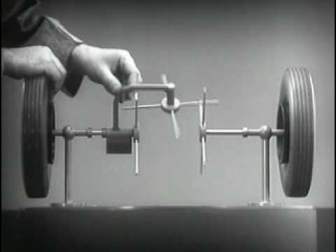
Around The Corner - How Differential Steering Works (1937) — US Auto Industry

US Auto Industry

Pivoting differential gears resolve the conflict between two-wheel traction and tire scrub by driving wheels at independent speeds, while low-center hypoid pinions lower drive shafts to maintain flat passenger floors.

AI-assisted summary of Around The Corner - How Differential Steering Works (1937) — original source. Check the original for full context.

Source published:

Key ideas

  • Automobiles require the outer wheel to spin faster than the inner wheel when negotiating turns, making solid drive axles unsuitable due to severe tire scrubbing and slipping. (0:01)
  • The differential resolves the cornering dilemma by evolving from a simple pivoting crossbar acting on axle spokes into a continuous assembly of meshed bevel pinions and side gears. (3:23)
  • A low-center hypoid drive connects the propeller shaft to the lower edge of the ring gear, flattening passenger floorboards and lowering the vehicle's center of gravity while improving gear meshing. (6:47)

Detailed notes

## Background Published on YouTube by the US Auto Industry channel on September 16, 2009, this 1937 educational film explains the fundamental mechanics of the automobile differential. The accompanying description highlights how differential steering enables a vehicle to navigate turns without wheel slippage, alongside a conceptual overview of differential steering and torque vectoring.

## TL;DR The presentation introduces the fundamental geometric dilemma of cornering, where an automobile's outer wheels must travel a greater distance and spin faster than the inside wheels without sacrificing engine power or causing tire scrub. Through a deliberate physical model, it deconstructs the differential down to two separate axles with single spokes, progressively evolving the mechanism into pivoted crossbars, continuous intermeshing gear teeth, and opposing spider bevel pinions. It concludes by detailing how engine torque is delivered to the differential assembly via a low-center hypoid ring and pinion drive, which simultaneously optimizes passenger floor space, lowers vehicle center of gravity, and improves gear durability.

## Atmosphere & style The presentation carries the crisp, authoritative charm of classic mid-century industrial cinema, pairing an upbeat orchestral fanfare with calm, methodical voiceover narration. Watching the mechanical apparatus take shape feels mesmerizing and intuitively satisfying, stripping away industrial complexity through simple, tangible physical demonstrations. The tone is deliberate, patient, and admiring of precision engineering, transforming what seems like a baffling mechanical puzzle into an elegant, common-sense solution.

## Bulletin - [00:01](https://www.youtube.com/watch?v=yYAw79386WI&t=1s) Automobiles require the outer wheel to spin faster than the inner wheel when negotiating turns, making solid drive axles unsuitable due to severe tire scrubbing and slipping. - [03:23](https://www.youtube.com/watch?v=yYAw79386WI&t=203s) The differential resolves the cornering dilemma by evolving from a simple pivoting crossbar acting on axle spokes into a continuous assembly of meshed bevel pinions and side gears. - [06:47](https://www.youtube.com/watch?v=yYAw79386WI&t=407s) A low-center hypoid drive connects the propeller shaft to the lower edge of the ring gear, flattening passenger floorboards and lowering the vehicle's center of gravity while improving gear meshing.

## Key takeaways - [00:01](https://www.youtube.com/watch?v=yYAw79386WI&t=1s) During a turn, outer wheels travel along a longer arc and must rotate faster than inner wheels to avoid skidding. - [01:00](https://www.youtube.com/watch?v=yYAw79386WI&t=60s) Horse-drawn wagons avoided wheel bind because their wheels rotated freely on dead axles without engine drive input. - [01:25](https://www.youtube.com/watch?v=yYAw79386WI&t=85s) Early attempts to drive only one rear wheel resulted in poor road grip and insufficient traction under heavy loads. - [01:45](https://www.youtube.com/watch?v=yYAw79386WI&t=105s) Rigidly locking both wheels to a single live axle forces tires to scrub, slip, and slide whenever departing from a straight path. - [02:15](https://www.youtube.com/watch?v=yYAw79386WI&t=135s) The differential is mounted in the rear axle specifically to allow both driven wheels to rotate at different speeds simultaneously. - [03:23](https://www.youtube.com/watch?v=yYAw79386WI&t=203s) A rigid crosspiece connecting opposing axle spokes drives both wheels in a straight line but binds entirely if one wheel is halted. - [04:15](https://www.youtube.com/watch?v=yYAw79386WI&t=255s) Mounting the crossbar on a center pivot allows it to swing and walk past a stopped wheel, continuing to power the opposite wheel. - [04:50](https://www.youtube.com/watch?v=yYAw79386WI&t=290s) Multiplying spokes and crossed pivot bars creates uninterrupted power delivery throughout continuous wheel rotation. - [05:40](https://www.youtube.com/watch?v=yYAw79386WI&t=340s) Filling the spoke gaps and curving them into bevel gear teeth creates smooth, continuous, and quiet mechanical surface contact. - [06:20](https://www.youtube.com/watch?v=yYAw79386WI&t=380s) Adding a second opposing bevel pinion gear balances the driving load across the differential carrier housing. - [06:47](https://www.youtube.com/watch?v=yYAw79386WI&t=407s) Engine power is transferred from the transmission through a drive pinion meshed with a large ring gear bolted to the differential carrier. - [07:15](https://www.youtube.com/watch?v=yYAw79386WI&t=435s) A centerline drive shaft would raise vehicle height or create an intrusive interior floor hump that shrinks cabin and luggage space. - [07:50](https://www.youtube.com/watch?v=yYAw79386WI&t=470s) Lowering the drive pinion to the bottom edge of the ring gear enables a flat floor, lower vehicle roofline, and reduced center of gravity. - [08:25](https://www.youtube.com/watch?v=yYAw79386WI&t=505s) The hypoid low-center drive setup enhances gear durability and quietness by providing smoother, larger contact surfaces between teeth.

## Detailed walkthrough ### [00:01](https://www.youtube.com/watch?v=yYAw79386WI&t=1s) The Problem of Turning a Corner

Following an upbeat musical opening accompanying precision motorcycle drill teams, the narrator illustrates the physical necessity of varying speeds during a turn. Moving in coordinated rank and file demands precise execution: “Formations like these require long hours of intensive drilling and careful judgment when the troop goes around the corner the riders on the outside of the turn have to adjust their speed to keep even with the riders on the inside.” Because the outer path follows a broader arc, “the man on the outside has to ride a lot farther and a lot faster in order to keep up with the parade.”

The exact same geometric challenge applies to wheeled road vehicles. Whenever an automobile navigates a turn, the outside wheels have to travel a greater distance within identical time limits compared to the inside wheels, meaning they must rotate faster. In horse-drawn wagons, this presented no issue because wheels were mounted freely on dead axles. Early automobiles attempted a simple solution by driving only a single rear wheel, leaving the other to spin independently. However, driving just one wheel meant poor road grip and insufficient traction under heavy loads. Conversely, locking both wheels rigidly to a single live axle caused severe tire scrubbing, slipping, and sliding around turns. The engineering dilemma demanded driving both wheels while still permitting them to rotate at different speeds. As the narrator explains: “The device which makes this possible is a part of the rear axle it is called the differential because it can drive the rear wheels at different speeds.”

- The outer wheel must cover a longer radial distance than the inner wheel during a curve. - Freely spinning wagon wheels avoid binding because neither wheel is mechanically linked to an engine drive. - Single-wheel drive failed in early motorcars due to lack of traction. - A solid, locked axle forces tires to scuff and slip whenever the car departs from a straight line.

---

[03:23](https://www.youtube.com/watch?v=yYAw79386WI&t=203s) Conceptual Evolution: From Spokes to Differential Gears

While the finished mechanism appears daunting, its core concept is built step-by-step from fundamental mechanical elements: “The differential looks complicated but once we understand its principle it is amazingly simple.” The demonstration begins with two co-axial independent stub axles, each terminating in a road wheel on the outer end and a single radial spoke on the inner end. Placing a rigid horizontal crosspiece between the two opposing spokes allows a person to rotate both wheels forward at identical rates. Mount this crosspiece into a free-wheeling circular support ring, and rotating the ring rotates both wheels together. However, a rigid crosspiece suffers from the exact same flaw as a locked axle: if one wheel stops, the entire support locks solid, and neither wheel can turn faster than the other.

```mermaid flowchart TD accTitle: Evolution of Differential Gears accDescr: Step-by-step mechanical progression from independent spokes to fully formed bevel gears.

subgraph Primitive["Spoke & Pivot Phase"] A["Two Separate Axles with Spokes"] --> B["Rigid Crosspiece on Carrier"] B --> C["Pivoted Swinging Crossbar"] C --> D["Multiple Crossbars and Spokes"] end

subgraph Refined["Gear Tooth Phase"] D --> E["Narrow Intermeshing Spokes"] E --> F["Full-Width Curved Gear Teeth"] F --> G["Opposed Pinion Bevel Gears"] end ```

To permit relative motion, the rigid crosspiece is placed on a center pivot, enabling it to swing back and forth. Now, if one wheel is stopped, the crossbar pivots on its axis, walking past the halted spoke while driving the opposite wheel forward. But a single bar swings out of contact once turned too far: “We need another crossbar and more spokes to carry on the job.” By adding multiple spokes around each axle hub and crossing pivot bars in the center, continuous rotation is maintained even while turning. When traveling straight, the pivot bars remain perpendicular without pivoting; when cornering, they rock and swing to drive the differential speeds.

To make the assembly practical for heavy automotive duty, the engineering steps progress naturally: - Spaces between the thin spokes are filled in to eliminate jerky, abrupt engagements. - The spokes are broadened and shaped into curved gear teeth to guarantee firm, continuous, and quiet surface contact. - The primitive crossbars become bevel spider pinions, and the axle spokes become bevel side gears. - An identical opposing pinion gear is installed opposite the first to share mechanical driving loads across the differential carrier.

---

[06:47](https://www.youtube.com/watch?v=yYAw79386WI&t=407s) Power Delivery and the Low-Center Hypoid Drive

Once the differential gear assembly is complete, engine power must be introduced to rotate the outer carrier. A large ring gear is fastened to the revolving housing, driven by a smaller drive pinion connected to the propeller shaft extending from the engine and transmission. While a straightforward center-mounted pinion aligns directly with the axle centerline, this configuration poses serious ergonomic problems for vehicle design. Running a straight drive shaft down the center of the car necessitates raising the entire cabin floor, which either shrinks passenger headroom or forces the car body to sit uncomfortably high off the ground.

Dropping the passenger floor down over a high-center drive shaft creates an intrusive transmission and propshaft tunnel: “A shaft in the middle of the floor of an automobile would be inconvenient for passengers and would be awkward for carrying luggage.” Automotive engineers resolved this conflict by lowering the drive shaft connection point to the bottom edge of the ring gear—implementing a hypoid low-center drive. This lower pinion axis drops the drive line cleanly beneath the floorboards, allowing the vehicle to have a low center of gravity, flat floor space, and a sleek profile without cramping interior passenger accommodations.

```mermaid flowchart LR accTitle: Drive Shaft Layout Comparison accDescr: Comparison of high centerline drive versus low-center hypoid drive.

subgraph HighCenter["Centerline Drive Design"] H1["High Drive Shaft"] --> H2["Axle Centerline"] H1 --> H3["Intrusive Floor Tunnel / High Body"] end

subgraph LowCenter["Low-Center Drive Design"] L1["Dropped Drive Shaft"] --> L2["Bottom of Ring Gear"] L1 --> L3["Flat Interior Floor & Lowered Chassis"] end ```

Beyond cabin packaging advantages, lowering the driving pinion delivers superior gear meshing characteristics: “The new low Center Drive makes the rear axle quieter stronger and more durable because it gives better smoother contact between the gears.” The narrator emphasizes that every casting, pinion, and shaft in the modern rear axle assembly is over-engineered to endure stresses far exceeding routine driving demands: “Every part of the rear axle has been built to withstand strains far greater than it will ever meet on the straightaway more around the corner.”

## Notable quotes > [03:23](https://www.youtube.com/watch?v=yYAw79386WI&t=203s) The differential looks complicated but once we understand its principle it is amazingly simple.

## Mentioned Chevrolet, US Auto Industry, Wikipedia

## Video description How the automobile differential allows a vehicle to turn a corner while keeping the wheels from skidding.

Differential steering From Wikipedia, the free encyclopedia https://en.wikipedia.org/wiki/Differential_steering

Differential steering is the means of steering a land vehicle by applying more or less drive torque to one side of the vehicle than the other. Differential steering is the primary means of steering tracked vehicles, such as tanks and bulldozers, is also used in certain wheeled vehicles commonly known as skid-steer, and even implemented in some automobiles, where it is called torque vectoring, to augment steering by changing wheel direction relative to the vehicle. Differential steering is distinct from torque steer, which is usually considered a negative side effect of drive-train design choices.

#DifferentialSteering #Chevrolet

[Source](https://www.youtube.com/watch?v=yYAw79386WI)

中文简报

车企采用差速齿轮消除过弯滑移 可旋转的差速齿轮通过以独立转速驱动车轮,化解了两轮牵引力与轮胎刮擦之间的冲突;同时,低偏心准双曲面小齿轮降低了传动轴高度,保持乘客舱地板平整。 本次展示介绍了汽车过弯时的基本几何困境:外侧车轮必须比内侧车轮行驶更长距离并以更快速度旋转,同时不能牺牲发动机动力或引起轮胎刮擦。展示通过精细的物理模型,将差速器解构为带有单根辐条的两根独立车轴,并逐步将该机构演变为可旋转横杆、连续互相啮合的轮齿以及相对的行星伞齿轮。展示最后详述了发动机扭矩如何通过低偏心准双曲面主减速齿轮传递至差速器总成,该方案同时优化了乘客舱地板空间、降低了车辆重心,并提高了齿轮的耐用性。 汽车在转弯时需要外侧车轮比内侧车轮转得更快,这使得刚性整体驱动桥因会导致严重的轮胎刮擦和滑移而不再适用。 (0:01) 差速器化解了过弯困境,其演进过程是从作用于车轴辐条上的简单可旋转横杆,逐步发展为由互相啮合的伞齿轮与半轴齿轮构成的连续总成。 (3:23) 低偏心准双曲面传动装置将传动轴连接至盆齿的下边缘,在改善齿轮啮合的同时,平整了乘客舱地板并降低了车辆重心。 (6:47)

Reading summary

The US Auto Industry's 1937 educational presentation demonstrates how the automotive differential resolves the kinematic conflict of driving both rear wheels while allowing them to rotate at varying speeds around corners, tracing the mechanism's design from basic pivoting spokes to hypoid bevel gears. Geometric Conflict of Turning Driven Wheels (0:01) When navigating a turn, a vehicle's outer wheels trace a wider arc and must travel farther and faster than the inside wheels within the same time frame. In horse-drawn wagons, this disparity caused no issue because the wheels spun freely on dead axles without an engine connection. Early motorcars struggled to replicate this adaptability. Driving only a single rear wheel resulted in poor road grip and insufficient traction under heavy loads, whereas locking both wheels rigidly to a single live axle forced the tires to scrub, slip, and scuff whenever the vehicle departed from a straight line. Resolving this dilemma required an axle mechanism that could drive both wheels while permitting independent rotational speeds. Mechanical Progression from Spokes to Bevel Gears (3:23) The operating concept is demonstrated by mounting independent stub axles with radial spokes driven by a horizontal crossbar housed inside a rotating carrier ring. While a rigid crossbar locks both wheels together identically to a solid axle, placing the crossbar on a center pivot allows it to swing, walking past a halted spoke on one side while continuing to drive the opposite wheel forward. Because a single pivoting bar swings out of engagement as it turns, adding multiple spokes and crossed pivot bars ensures continuous engagement. On straight paths, the pivot bars remain perpendicular without swinging; during turns, they rock back and forth to distribute relative movement. To make this assembly suitable for practical automotive loads, the design replaces thin spokes with continuous, curved gear teeth to guarantee quiet, uniform contact. This converts the primitive axle spokes into bevel side gears and the rotating pivot bars into bevel spider pinions. A second, opposing pinion gear is positioned opposite the first to share driving loads evenly across the differential carrier. Packaging and Durability Gains of Hypoid Drives (6:47) Engine torque is introduced to the differential carrier by fastening a large ring gear to the housing, which is driven by a drive pinion linked to the propeller shaft. Aligning this pinion directly along the axle centerline created ergonomic packaging challenges, requiring an intrusive floor tunnel or a raised chassis that reduced passenger headroom and luggage space. Automotive engineers resolved this issue by adopting a hypoid low-center drive, which meshes the drive pinion at the bottom edge of the ring gear. Lowering the drive line beneath the floorboards enabled flat interior floors, a lowered vehicle center of gravity, and a sleeker exterior profile without cramping passenger quarters. According to the presentation, this low-center geometry also provides smoother gear contact, creating a quieter and more durable rear axle built to withstand loads far beyond normal driving conditions. The presentation concludes that through the combination of bevel differential gearing and a low-center hypoid drive, modern rear axles successfully resolve the trade-offs between continuous power delivery, turning agility, passenger compartment ergonomics, and long-term mechanical durability.

精炼阅读摘要

本片系统阐明了汽车转弯时内外侧车轮存在差速需求的几何原理,展示了差速器如何通过由杠杆辐条逐步演化为伞齿轮的机械构造,在持续传递动力给两侧车轮的同时允许其以不同转速旋转,并解析了准双曲面低中心驱动在优化座舱空间与传动耐用度方面的工程价值。 转弯几何学与驱动车轮的两难境地 (0:01) 影片以摩托车特技编队的转弯动作作为直观类比:在整齐队列拐弯过程中,外侧骑手沿半径更大的圆弧行驶,必须比内侧骑手骑行更长距离并保持更快速度,才能维持队列整齐。这一几何学规律同样完全适用于轮式公路车辆。汽车转弯时,外侧车轮需要在相同时间内走过比内侧车轮更长的路程,因此外侧车轮的旋转速度必须高于内侧车轮。在传统的马拉货车中,车轮独立空转安装在死轴上,彼此之间没有机械驱动关联,因此不会产生转弯阻滞问题。 然而,机动车需要依靠动力轴驱动行驶,这在早期引发了棘手的工程两难。早期汽车尝试仅驱动单个后轮,让另一侧车轮自由旋转,但这导致抓地力极差,在重载条件下无法提供足够的牵引力。相反,如果将两侧车轮刚性锁止在同一根传动轴上,车辆一旦偏离直线轨迹,车轮就会出现严重的轮胎磨损、打滑与侧滑。汽车工程亟需一种既能驱动两侧车轮、又能允许二者以不同速度旋转的机械装置,安装于后桥的差速器正是为化解这一动力与几何矛盾而诞生的核心部件。 从基础杠杆到差速伞齿轮的演进 (3:23) 虽然成品的差速器看起来结构复杂,但其设计原理从基础机械部件逐步推导而来极其简明。演示首先设置了两根同轴但相互独立的半轴,外端安装车轮,内端各带一根径向辐条。在两根辐条之间架设一根刚性水平横梁,并将横梁固定在可自由旋转的环形支架内,当转动环形支架时,两侧车轮便会以完全相同的速度向前同步旋转。然而,刚性横梁存在与整体刚性轴相同的致命缺陷:只要其中一个车轮停止转动,整个支架就会被彻底卡死,两个车轮都无法产生相对差速。 为了允许相对运动,设计将刚性横梁改换为带中心枢轴的摆动式横杆。当其中一侧车轮被固定时,横杆绕自身枢轴摆动,在越过静止辐条的同时推动另一侧车轮继续加速前行。但单一横杆转动幅度过大后便会脱离接触,因此工程上在轮毂四周增加了多根辐条,并在中心交叉布置多个摆动横杆,确保在持续转弯时始终有构件啮合传力。当车辆直线行驶时,横杆保持垂直不发生摆动;车辆转弯时,横杆则不断摆动以维持差速运转。 差速机构的齿轮化与载荷平衡 (3:23) 为了让这一机构满足汽车实际的高负荷工作要求,原始的辐条与横杆经历了进一步的齿轮化改良。首先,工程人员填补了细辐条之间的间隙,以消除动力啮合时的顿挫与剧烈冲击;随后,辐条被进一步加宽并塑造成弧形齿廓,演进为标准的齿轮齿面,以确保动力接触平稳、连续且低噪音。最终,中心的原型横杆演变为差速器行星伞齿轮,而半轴内端的辐条则演变为半轴伞齿轮。 此外,机构在差速器壳体内与第一个行星伞齿轮正相对的位置安装了另一个完全相同的对置齿轮。通过双行星齿轮结构,差速器壳体向半轴传递动力时的机械载荷得以均匀分担,从而大幅提高了整个总成在恶劣工况下的抗疲劳强度与承载稳定性。 动力导入与座舱人机工程学的冲突 (6:47) 完成差速齿轮的装配后,必须将发动机动力引入并带动外部壳体旋转。差速器壳体外部固定了一个大型主被动大齿圈,由连接至发动机与变速箱传动轴的小主动齿轮负责驱动。如果采用简单的中心驱动布局,主动小齿轮的轴线将直接对齐后桥中心线。然而,这一传统直连方案给乘员舱人机工程学带来了严重挑战:直通车身中央的高位传动轴迫使整个底盘离地间隙升高或压缩车内头部空间;若将乘员舱地板向下延伸,传动轴则会在车内地板正中形成隆起的通道,严重影响乘客腿部舒适度与行李摆放便利性。 准双曲面低中心驱动的综合效益 (6:47) 为化解座舱空间与传动轴布置的冲突,汽车工程师采用了将驱动轴连接点移至大齿圈底边缘的准双曲面低中心驱动设计。这一改进使传动轴高度显著降低至地板以下,让整车能够同时兼顾低重心、纯平内部底板以及流畅的车身外形,完全避免了车内空间的狭窄压抑。解说员同时强调,降低驱动小齿轮位置还改善了齿轮啮合状态,使轮齿接触更顺畅、平稳,进而使后桥运转更加安静、坚固且耐磨。据解说员所述,现代后桥总成的每一个铸件、齿轮和轴系在设计制造时都预留了充分的承载余量,能够承受远超常规直线行驶或转弯工况的机械应力。 该片系统呈现了差速器从初级杠杆辐条到现代双行星伞齿轮的逻辑推导过程,并阐释了准双曲面低中心驱动如何协调传动机构与车身工程。影片聚焦于几何原理解析与机械结构的定性演示,解说员强调其各构件均经过超负荷强化设计,展现了20世纪30年代汽车后桥传动技术的工程成熟度。

Detailed notes — zh

## Background 该视频由 YouTube 频道“US Auto Industry”于 2009 年 9 月 16 日发布,原片制作于 1937 年。根据页面简介,本片主要展示了汽车差速器的工作原理,解释其如何让车辆在顺利转弯的同时防止车轮打滑磨损。 ## TL;DR 影片首先以骑兵队列转弯时内外圈行驶距离不同的物理规律为切入点,剖析了汽车转弯时外侧车轮转速必须快于内侧车轮的基本运动学原理。随后,演示人员利用精妙的木质与金属教学台架,从左右独立断开的车轴与单根推杆开始,逐步引入枢轴横梁以实现差速摆动。通过不断增加交叉辐条并消除间隙,机构最终顺畅演化为能够无缝啮合的现代差速器伞齿轮结构。最后,影片还探讨了后桥传动轴在底盘空间中的布局矛盾,并展示了通过下移啮合位置来降低车身重心、平整座舱地板的工程解决方案。 ## Atmosphere & style 全片洋溢着 1930 年代工业科普黄金时期的典雅与从容,伴随着轻快悠扬的管弦配乐,呈现出一种兼具严密逻辑与古典机械美感的视听体验。旁白语调沉稳、咬字清晰,以步步为营的启发式教学带着观众抽丝剥茧,将原本深奥晦涩的机械机构拆解得直观透明。实体台架的直观演化充满了纯粹的工程趣味,让人在目睹简易木棍演变为精密齿轮的过程中由衷体会到工业设计化繁为简的精妙与震撼。 ## Bulletin - [00:01](https://www.youtube.com/watch?v=yYAw79386WI&t=1s) 汽车转弯时外侧车轮转弯半径更大,相同时间内行经距离更长,因而旋转角速度必须高于内侧车轮才能避免轮胎在地面拖拽打滑。 - [03:03](https://www.youtube.com/watch?v=yYAw79386WI&t=183s) 早期汽车的单轮驱动因抓地力不足被淘汰,而刚性双轮死锁轴在过弯时无法调节轮速,促使工程师发明了兼具双向驱动与独立转速调节能力的差速器机构。 - [04:47](https://www.youtube.com/watch?v=yYAw79386WI&t=287s) 差速器原理可通过“枢轴横梁与辐条”模型推导:直行时中心横梁不自转并同速推移双轮,过弯产生转速差时横梁绕自身枢轴摆动,逐步演化为啮合的伞齿轮与行星齿轮组。 - [07:21](https://www.youtube.com/watch?v=yYAw79386WI&t=441s) 为避免高位传动轴在降低车身时挤占乘员舱腿部空间,工程师引入低位啮合的准双曲面齿轮驱动,在压低整车重心的同时保持车内地板平整。 ## Key takeaways - [00:01](https://www.youtube.com/watch?v=yYAw79386WI&t=1s) 如骑兵队列转弯所示,转弯路径上外侧车轮在相同时间内行经的弧线长度远大于内侧,必须拥有更快的转速以维持正常运动学规律。 - [00:01](https://www.youtube.com/watch?v=yYAw79386WI&t=1s) 传统马车各轮在轴上独立自由转动因而不受差速影响,但汽车需要发动机提供动力驱动,无法照搬无动力的松散轮轴结构。 - [00:01](https://www.youtube.com/watch?v=yYAw79386WI&t=1s) 早期单轮驱动方案将全部牵引载荷施加于单一轮胎,导致抓地力匮乏且驱动效能低下,迅速被历史淘汰。 - [00:01](https://www.youtube.com/watch?v=yYAw79386WI&t=1s) 将左右后轮刚性固定在同一根车轴上会导致转弯时轮速无法自适应,迫使其中一侧轮胎在地面强行滑移磨损。 - [03:03](https://www.youtube.com/watch?v=yYAw79386WI&t=183s) 差速器的核心工程目标是让单一动力源在同时驱动左右车轮的前提下,允许两侧车轮以不同的角速度独立运转。 - [03:03](https://www.youtube.com/watch?v=yYAw79386WI&t=183s) 在断开的两根半轴末端加设辐条并用固定横梁推动,可实现直行同步驱动,但在过弯或单侧受阻时横梁会发生彻底卡死。 - [04:47](https://www.youtube.com/watch?v=yYAw79386WI&t=287s) 将驱动横梁改为中间带枢轴的活动结构,允许其绕支点摆动,从而在单侧车轮制动时借助静止辐条反向驱动另一侧车轮加速旋转。 - [04:47](https://www.youtube.com/watch?v=yYAw79386WI&t=287s) 单根枢轴横梁摆动幅度过大会脱开辐条导致动力中断,通过在圆周上密集阵列交叉横梁与辐条可实现不间断传动。 - [04:47](https://www.youtube.com/watch?v=yYAw79386WI&t=287s) 将密集辐条的接触面演化为厚实的渐开线斜面,即构成了汽车差速器内部的核心部件——伞齿轮总成。 - [04:47](https://www.youtube.com/watch?v=yYAw79386WI&t=287s) 在对称轴侧增加第二枚行星小齿轮,可有效分担传动扭矩并提升整个差速器运转的机械平顺度与可靠性。 - [04:47](https://www.youtube.com/watch?v=yYAw79386WI&t=287s) 发动机动力通过主动小齿轮传递给差速器外部的大齿圈,大齿圈带动空转支架转动,进而带动内部齿轮驱动半轴。 - [07:21](https://www.youtube.com/watch?v=yYAw79386WI&t=441s) 传统传动轴中心对齐布局迫使车身在“高重心笨拙外形”与“车内地板隆起侵占乘客空间”之间做出妥协。 - [07:21](https://www.youtube.com/watch?v=yYAw79386WI&t=441s) 准双曲面齿轮设计将传动轴啮合点向下平移,不仅消除了乘员舱中央鼓包、降低了整车重心,还提升了齿面接触重合度与静音耐久性。 ## Detailed walkthrough ### [00:01](https://www.youtube.com/watch?v=yYAw79386WI&t=1s) 骑兵编队与转弯速度的内在物理规律 影片在轻快悠扬的管弦配乐中拉开序幕,画面呈现了一支骑兵队在宽阔场地上进行严整的队列操演。旁白指出,完成这样整齐划一的编队行进绝非易事,背后需要长时间的刻苦训练与极为精准的距离判断。当整个骑兵纵队开始向一侧转弯时,由于内外侧所处的回转半径不同,外侧的骑手必须时刻调整自己的速度,以保持与内侧骑手齐头并进的队形。 ```mermaid flowchart LR accTitle: Cornering Path Difference accDescr: Diagram showing inner versus outer turning radii and speeds subgraph Turning["车辆或编队转弯"] direction TB In["内侧轨迹 (半径较短)"] --> InSpd["移动距离短 / 转速低"] Out["外侧轨迹 (半径较长)"] --> OutSpd["移动距离长 / 转速高"] end ``` 这种运动学现象正是后续汽车机械结构的现实基础。旁白清晰地阐述了内外侧的动态关系:“The outside wheels must spin faster than the wheels on the inside because they have a greater distance to travel in the same length of time.” 这意味着,在相同的时间跨度内,外侧行驶的轮子必须克服更长的一段弧线,因此它的旋转角速度必须明显大于内侧轮子。 - 传统马车在转弯时完全没有这个问题,因为马车的各个车轮都松散地装在轴上,能够独立在车轴上自由旋转。 - 早期汽车的后轮虽然彼此独立,但往往只依靠一台发动机驱动其中的单侧车轮。 - 单轮驱动暴露出严重缺陷:驱动轮要承担整车前进的全部牵引任务,导致轮胎无法在路面上获得足够的抓地力,很快便遭到淘汰。 - 如果简单地将两侧后轮直接刚性锁死在同一根车轴上,转弯时由于转速无法调节,其中一个轮子必然会被迫在地面上拖拽打滑。 --- ### [03:03](https://www.youtube.com/watch?v=yYAw79386WI&t=183s) 差速器的基础概念与“横梁-辐条”模型 为了解决既要由发动机同时驱动两个后轮、又要在转弯时不发生轮胎侧滑或打滑的工程矛盾,工程师在后桥中央设计了一个专门的机构——差速器。旁白指出,这套装置之所以得名,是因为它能够以不同的速度驱动后轮。尽管它第一眼看上去精密复杂,但只要拆解其基础原理,逻辑其实异常简朴直观。 ```mermaid flowchart TD accTitle: Differential Evolution accDescr: Step by step model of the differential mechanism subgraph Stage1["两端断开的独立轮轴"] A["左轮 + 左轴辐条"] B["右轮 + 右轴辐条"] end subgraph Stage2["驱动横杆与支架"] C["固定横梁 (无法差速,锁死)"] D["中心枢轴横梁 (可自由左右摆动)"] end Stage1 --> C C -->|改进为枢轴连接| D D -->|"多组辐条填满 -> 形成轮齿"| Gears["差速器齿轮啮合"] ``` 演示人员搭建了一个极具启发性的木质与金属教学台架。两个车轮分别固定在左右断开的两根独立半轴上,并由外部支架支撑,使它们能够自由地以不同速度旋转。在两根半轴的内端各安装一根竖向“辐条”,通过拨动辐条就能分别带动对应的轮子转动。 随后,演示者加入了一根横向的平木条(横梁)。将横梁同时推向左右两根辐条时,两个车轮便以相同的速度朝同一方向转动。为了让这根横梁能够持续施压,外部增加了一个套在轴上的旋转支架。但旁白特别强调了一个关键细节:该支架并未锁死在车轴上,而是可以在轴上自由空转。转动支架即可带动横梁推着两根辐条向前跑,使两个轮子同速前进。 然而,一旦遇到转弯工况,这种刚性横梁便彻底失效。由于两根辐条无法产生相对位移,系统无法以一快一慢的方式分别驱动车轮;若用手按停其中一个轮子,另一个轮子也会瞬间被卡死动弹不得。 --- ### [04:47](https://www.youtube.com/watch?v=yYAw79386WI&t=287s) 引入枢轴横梁与齿轮演化 为了打破刚性死锁,演示者将安装在支架上的横梁改为中间带有枢轴(Pivot)的结构,让横梁能够以中心为支点向前后自由摆动。这一改变带来了质的飞跃:当车辆直行时,枢轴横梁不发生倾斜,推着两侧辐条以相同速度旋转;而一旦外力阻止了其中一个车轮的转动,横梁便会绕着自身的枢轴顺势倾斜旋转,从而在静止车轮的辐条上借力,继续推动另一侧的车轮自由旋转。 但这套极简模型仍有致命缺陷:横梁摆动的角度一旦过大,就会彻底脱离辐条的驱动范围,导致传动中断。解决方式是增加更多相互交错的横梁与辐条。演示者逐步在两端轴承上安装更多的交叉杆和辐条,让前一根横梁摆动脱离前,下一根横梁能够立即无缝衔接。 ```mermaid flowchart LR accTitle: Mechanical Transformation to Gears accDescr: Visual transition from spokes and crossbars to bevel gears S1["离散木质辐条 + 交叉推杆"] -->|"增加数量 / 消除间隙"| S2["密布的厚实体块"] S2 -->|"切削倾斜接触边缘"| S3["伞齿轮 (Bevel Gears)"] S3 -->|"对侧加入对称行星齿轮"| S4["完整汽车差速器总成"] ``` 为了彻底消除间距过大所引发的断续与顿挫,工程师将辐条之间的空隙彻底填满,并将接触端切削出斜向的渐开线受力面。转瞬之间,原本简陋的辐条与横梁便演化成了厚实、强韧的伞齿轮(Differential Gears)。旁白在此概括了差速器最根本的工作状态:“As long as both wheels are free to turn, the bars do not swing on their pivot and the wheels move at the same speed.” 只要两侧车轮遇到的阻力一致,中间的齿轮就不会绕自身轴线自转;唯有两侧车轮出现转速差时,中心齿轮才会发生自转进行补偿。 - 在轴的对侧额外增加了一个完全对称的行星小齿轮,让两只齿轮分担驱动扭矩,从而使运转更加平稳耐用。 - 为了从发动机引入动力,差速器支架外侧加装了一圈巨大的从动齿轮(主减速器大齿圈),由来自发动机动力源的主动小齿轮与之垂直啮合驱动。 --- ### [07:21](https://www.youtube.com/watch?v=yYAw79386WI&t=441s) 底盘空间冲突与低重心驱动设计 在差速器模型完善之后,影片将视角转向其在整车底盘中的实际工程布置。将动力由车头发动机传递到后桥差速器,需要一条贯穿车底的传动轴。在传统的早期设计中,传动轴通常正对差速器的中心线水平接入。这种布局给车身设计带来了两难抉择: 1. **垫高车内地板**:如果为了避让高耸的传动轴而抬高乘员舱底板,要想保证头部空间,车顶就必须造得极高,使得整车重心过高且造型笨拙。 2. **压低车内地板**:如果强行降低底盘和车顶高度,传动轴就会像一道巨大的驼峰横贯在车厢正中央,不仅严重挤占乘客的腿部空间,也极大妨碍了行李与货物的规整放置。 针对这一空间与实用性的冲突,工程师研发出了“低位中心驱动”(Low Center Drive,即准双曲面齿轮设计)。传动轴从原本正对车桥中心线的位置被整体向下平移,从差速器齿圈的偏下部位实现低位啮合。 - 这种结构使得传动轴不再侵占乘员舱空间,使得汽车能够同时实现更低趴贴地的车身姿态、更低的整车重心与更宽敞平整的座舱环境。 - 准双曲面齿轮啮合增大了齿面接触重合度,使后桥齿轮运转更加平顺、安静且抗冲击负荷能力更强。 - 旁白最后坚定地总结了现代后桥的耐用性:“Every part of the rear axle has been built to withstand strains far greater than it will ever meet on the straightaway or around the corner.” ## Notable quotes > [00:01](https://www.youtube.com/watch?v=yYAw79386WI&t=1s) The outside wheels must spin faster than the wheels on the inside because they have a greater distance to travel in the same length of time. — 旁白 > [07:21](https://www.youtube.com/watch?v=yYAw79386WI&t=441s) Every part of the rear axle has been built to withstand strains far greater than it will ever meet on the straightaway or around the corner. — 旁白 ## Mentioned Around The Corner - How Differential Steering Works (1937), US Auto Industry, Chevrolet, Wikipedia, 差速器 (Differential), 伞齿轮 (Bevel Gears), 准双曲面齿轮 / 低位中心驱动 (Low Center Drive), 主减速器大齿圈 ## Video description How the automobile differential allows a vehicle to turn a corner while keeping the wheels from skidding. Differential steering From Wikipedia, the free encyclopedia https://en.wikipedia.org/wiki/Differential_steering Differential steering is the means of steering a land vehicle by applying more or less drive torque to one side of the vehicle than the other. Differential steering is the primary means of steering tracked vehicles, such as tanks and bulldozers, is also used in certain wheeled vehicles commonly known as skid-steer, and even implemented in some automobiles, where it is called torque vectoring, to augment steering by changing wheel direction relative to the vehicle. Differential steering is distinct from torque steer, which is usually considered a negative side effect of drive-train design choices. #DifferentialSteering #Chevrolet [Source](https://www.youtube.com/watch?v=yYAw79386WI)

Source quotes

[0:01] 旁白: The outside wheels must spin faster than the wheels on the inside because they have a greater distance to travel in the same length of time. [7:21] 旁白: Every part of the rear axle has been built to withstand strains far greater than it will ever meet on the straightaway or around the corner.

Source quotes

[3:23] The differential looks complicated but once we understand its principle it is amazingly simple.

Original transcript

[0:01] [Music] [0:08] [Music] [0:14] [Music] [0:24] [Music] [0:33] [Music] [0:44] [Music] [1:00] [Music] [1:11] [Music] [1:27] [Music] [1:37] [Music] [1:50] formations like these require long hours [1:53] of intensive drilling and careful [1:55] judgment when the troop goes around the [1:58] corner the riders on the outside of the [2:00] turn have to adjust their speed to keep [2:02] even with the riders on the inside the [2:06] man on the outside has to ride a lot [2:07] farther and a lot faster in order to [2:10] keep up with the parade the outside [2:14] wheels must spin faster than the wheels [2:16] on the inside because they have a [2:19] greater distance to travel in the same [2:21] length of time when a wagon turns a [2:24] corner the wheels can travel at [2:26] different speeds because each one can [2:28] turn freely on the axles and in the [2:32] early automobiles the rear wheels turn [2:34] separately and only one wheel was [2:37] connected to the engine but when only [2:40] one wheel was driven by the engine it [2:42] had to do all the work and it couldn't [2:45] get a good enough grip on the road to do [2:47] its job properly so the one wheel drive [2:50] was soon out of date but if two wheels [2:54] are locked on an axle so that they are [2:56] not free to turn separately one or the [2:59] other as to slide so engineers had to [3:03] find a way to connect both rear wheels [3:05] to the engine without sliding and [3:07] slipping on turns the device which makes [3:11] this possible is a part of the rear axle [3:14] it is called the differential because it [3:18] can drive the rear wheels at different [3:21] speeds the differential looks [3:23] complicated but once we understand its [3:26] principle it is amazingly simple these [3:29] two wheels are mounted on separate axles [3:32] and supported by a frame so that they [3:35] can revolve freely at different speeds [3:39] let's fasten a spoke on the inner end of [3:43] each axle so that by turning the sports [3:48] we can turn each wheel separately [3:55] with a bar or crosspiece we can turn [4:00] both wheels in the same direction at the [4:03] same rate of speed let's get something [4:07] to hold this bar in place so that it [4:09] will press against the spose notice that [4:13] this support is not locked to the axle [4:15] it turns freely now we can spin the [4:20] wheels by rotating the support this is [4:24] fine as long as both wheels are able to [4:26] turn at the same speed but let's see [4:30] what happens when we go around the [4:32] corner with this arrangement we cannot [4:35] drive one wheel faster than the other [4:40] and if we stop one wheel the other wheel [4:47] won't budge let's put this bar on a [4:52] pivot so that it can swing in either [4:56] direction [5:02] now the bar can still turn both wheels [5:06] at the same speed and because it pivots [5:11] it lets one wheel turn even when the [5:15] other is stopped but if turned too far [5:20] the bar will swing around until it won't [5:23] drive the spokes that tourney the wheel [5:26] we need another crossbar and more spokes [5:30] to carry on the job when we stop one [5:34] wheel the crossbars will continue to [5:38] push the spokes of the freewheel around [5:40] as long as both wheels are free to turn [5:45] the bars do not swing on their pivot and [5:49] the wheels move at the same speed now we [5:54] have the working principles of a [5:56] differential to adapt the model for use [5:59] in an automobile we will have to make a [6:02] few changes in order to reduce the jerky [6:06] action caused by wide spaces between the [6:09] spokes we will put in more spokes [6:16] further filling in the spaces between [6:19] the spokes gives steadier more [6:22] continuous action and changing the shape [6:24] gives firm constant contact now we can [6:30] make the gears thicker and stronger and [6:32] we have differential gears the edges are [6:37] cut so that they will fit together more [6:39] smoothly and silently [6:41] and another gear is added to share the [6:44] work of driving the axles the principle [6:47] is the same in order to turn the support [6:50] and drive the wheels we can fasten a [6:53] large gear here connected by a smaller [6:58] gear to a source of power [7:07] notice that the power is connected to [7:10] the differential at the center line we [7:15] can make our model more compact by [7:18] moving the gears closer together when we [7:21] put our differential in an automobile we [7:24] have to leave room for the driveshaft [7:25] which carries the power from the engine [7:29] we may build the floor of the car [7:31] above the driveshaft but if we do we [7:37] won't have much room inside unless we [7:39] make the top of the car high - of course [7:43] we could lower the floor and ceiling but [7:45] the driveshaft would be higher than the [7:47] floor this would have disadvantages our [7:51] shaft in the middle of the floor of an [7:53] automobile would be inconvenient for [7:55] passengers and would be awkward for [7:57] carrying luggage today engineers have [8:01] found a way to make the car roomier and [8:03] closer to the road without a clumsy [8:06] shaft above the floor the drive shaft [8:09] from the engine to the differential is [8:12] lowered out of the way and the drive [8:15] shaft is connected to the rear axle at [8:17] the bottom the new low Center Drive [8:20] makes the rear axle quieter stronger and [8:24] more durable because it gives better [8:27] smoother contact between the gears the [8:32] automobile of today with the low Center [8:34] Drive is stronger and more rugged every [8:39] part of the rear axle has been built to [8:42] withstand strains far greater than it [8:45] will ever meet on the straightaway more [8:47] around the corner [8:49] [Music]