D/A and A/D | Digital Show and Tell (Monty Montgomery @ xiph.org)
FL Studio
AI-assisted summary of D/A and A/D | Digital Show and Tell (Monty Montgomery @ xiph.org) — original source. Check the original for full context.
Source published:
Key ideas
- Digital-to-analog conversion does not produce a stair-step signal; under the Nyquist-Shannon sampling theorem, band-limited discrete samples yield exactly one mathematically continuous analog curve. (5:58)
- Bit depth determines the dynamic range and noise floor rather than waveform smoothness, with 16-bit audio outperforming professional analog reel-to-reel tape systems that peaked near 13 bits of effective resolution. (8:45)
- Applying dither during quantization decouples quantization error from the input signal, replacing harmonically correlated distortion with flat, predictable noise and allowing signals below half a bit to be preserved perfectly. (12:23)
- Digital systems are not bound to a timing resolution limited by the sample period; band-limited signals faithfully preserve sub-sample transient timing and reconstruct edges at arbitrary points between samples. (20:53)
Detailed notes
## Background Published on March 2, 2013, on YouTube by FL Studio, this video features Monty Montgomery from Xiph.org demonstrating digital audio principles. According to the page description, the presentation uses real audio gear, modern digital analysis, and vintage analog bench equipment to address the digital versus analog quality debate, explaining why 16-bit, 44.1 kHz digital signals reproduce audible sound with complete fidelity.
## TL;DR Monty Montgomery dismantles enduring digital audio myths by testing real signals through an analog-digital-analog loop using vintage analog laboratory equipment. He disproves the common "stair-step" misconception by demonstrating that band-limited discrete samples reconstruct into perfectly smooth continuous sine waves up to 20 kHz. The presentation explores how bit depth governs noise floors rather than geometric resolution, showing how dither eliminates harmonic distortion and preserves signals smaller than a single bit. Montgomery also clarifies the nature of band-limiting and Gibbs phenomenon ripples on square waves, proving that digital systems possess infinite sub-sample timing resolution rather than time-stepped limitations.
## Atmosphere & style The presentation carries the cozy, delightfully nerdy warmth of a late-night workbench session guided by a seasoned engineer who loves taking things apart. Montgomery's delivery is humble, dryly humorous, and reassuringly unpretentious, swapping audiophile mysticism for concrete oscilloscope traces and clunky vintage gear. Watching the green CRT phosphor lines smoothly track waveforms feels deeply satisfying, transforming abstract signal theory into an intuitive, visually conclusive reality check.
## Bulletin - [05:58](https://www.youtube.com/watch?v=cIQ9IXSUzuM&t=358s) Digital-to-analog conversion does not produce a stair-step signal; under the Nyquist-Shannon sampling theorem, band-limited discrete samples yield exactly one mathematically continuous analog curve. - [08:45](https://www.youtube.com/watch?v=cIQ9IXSUzuM&t=525s) Bit depth determines the dynamic range and noise floor rather than waveform smoothness, with 16-bit audio outperforming professional analog reel-to-reel tape systems that peaked near 13 bits of effective resolution. - [12:23](https://www.youtube.com/watch?v=cIQ9IXSUzuM&t=743s) Applying dither during quantization decouples quantization error from the input signal, replacing harmonically correlated distortion with flat, predictable noise and allowing signals below half a bit to be preserved perfectly. - [20:53](https://www.youtube.com/watch?v=cIQ9IXSUzuM&t=1253s) Digital systems are not bound to a timing resolution limited by the sample period; band-limited signals faithfully preserve sub-sample transient timing and reconstruct edges at arbitrary points between samples.
## Key takeaways - [03:39](https://www.youtube.com/watch?v=cIQ9IXSUzuM&t=219s) Analog test equipment reveals that digital signals converted back to analog emerge as continuous, smooth waveforms without stair steps, even up to the 20 kHz limit of human hearing. - [05:58](https://www.youtube.com/watch?v=cIQ9IXSUzuM&t=358s) Sampled digital signals are discrete-time values with no defined state between sample intervals; stair steps exist solely as software visualization conventions or intermediate zero-order hold states. - [05:58](https://www.youtube.com/watch?v=cIQ9IXSUzuM&t=358s) The Nyquist-Shannon sampling theorem guarantees that exactly one continuous band-limited waveform can pass through a set of discrete samples below half the sampling rate. - [08:45](https://www.youtube.com/watch?v=cIQ9IXSUzuM&t=525s) Sampling itself is mathematically lossless; quantization is the step that introduces noise by limiting amplitude precision to discrete levels. - [08:45](https://www.youtube.com/watch?v=cIQ9IXSUzuM&t=525s) Quantization noise behaves identically to analog magnetic tape hiss when using Gaussian dither, revealing that consumer cassette tapes possessed only 5 to 9 bits of dynamic range. - [12:23](https://www.youtube.com/watch?v=cIQ9IXSUzuM&t=743s) Truncating without dither causes quantization errors to correlate with the input signal, generating harmonic distortion spikes that rise above the flat noise floor. - [12:23](https://www.youtube.com/watch?v=cIQ9IXSUzuM&t=743s) Dither enables the complete preservation of sub-bit signals (such as 0.25 LSB), which would otherwise collapse to complete silence and 100% distortion through truncation. - [14:08](https://www.youtube.com/watch?v=cIQ9IXSUzuM&t=848s) Noise shaping shifts dithering energy out of the human ear's most sensitive 2 kHz to 4 kHz range and into higher frequencies, making dither perceptually quieter. - [14:08](https://www.youtube.com/watch?v=cIQ9IXSUzuM&t=848s) While shaped dither increases overall RMS noise power compared to unshaped truncation error, psychoacoustic curves ensure it sounds substantially quieter to the human ear. - [14:08](https://www.youtube.com/watch?v=cIQ9IXSUzuM&t=848s) At 16 bits, undithered distortion artifacts and dither noise sit roughly 100 dB below full-scale peaks, making dither a subtle safeguard rather than a catastrophic audio defect. - [17:23](https://www.youtube.com/watch?v=cIQ9IXSUzuM&t=1043s) Gibbs phenomenon ringing on square waves is an inescapable mathematical consequence of band-limiting above 20 kHz, not a distortion introduced by filter defects. - [17:23](https://www.youtube.com/watch?v=cIQ9IXSUzuM&t=1043s) Passing an already band-limited signal through an anti-aliasing low-pass filter a second time produces zero additional ripple or degradation. - [20:53](https://www.youtube.com/watch?v=cIQ9IXSUzuM&t=1253s) Digital audio timing resolution is continuous rather than quantized to sample intervals, allowing transitions and transients to be placed accurately between individual samples.
## Detailed walkthrough ### [00:03](https://www.youtube.com/watch?v=cIQ9IXSUzuM&t=3s) The Stair-Step Myth and Vintage Analog Bench Gear
Monty Montgomery introduces the motivation behind the demonstration: a few months prior, he authored an article examining digital audio and explaining why 24-bit/192 kHz audio downloads make little practical sense. In passing, the article mentioned that a digital waveform is not a stair step and that converting digital back to analog does not produce stair steps. Surprisingly, that single passing remark triggered the vast majority of feedback. Over half of the correspondence he received involved fundamental questions and confusion surrounding basic digital signal behavior. To clear up these misconceptions from first principles, Monty designs an experiment assuming the audience knows nothing about how digital signals behave—meaning digital test equipment cannot be trusted either.
To observe the signals purely through an analog lens, Monty sets up a workbench filled with vintage analog laboratory equipment. An HP 3325 synthesizer/function generator from 1978 serves as the analog signal source; Monty jokes that while it is heavy, bulky, power-hungry, and equipped with a loud cooling fan, units can still be found on eBay for barely more than the shipping cost. Signals are monitored in the time domain using a Tektronix 2246 oscilloscope from the mid-1990s—one of the finest analog scopes ever built. Frequency content is tracked via an HP 3585 analog spectrum analyzer. While these instruments contain large, rudimentary microcontrollers, the actual signal paths from physical input to CRT screen remain entirely analog.
- **Signal baseline:** The HP 3325 outputs a clean 1 kHz sine wave at 1 V RMS (2.8 V peak-to-peak), confirmed identically across the Tektronix scope and the HP 3585 spectrum analyzer. - **Spectrum baseline:** The analyzer reveals a trace of low-level white noise and minor harmonic distortion, with the highest harmonic peak roughly 70 dB below the fundamental frequency.
```mermaid flowchart LR accTitle: Analog and Digital Signal Flow accDescr: Diagram tracing the signal from the analog generator through conversion and back to output scopes. subgraph Input ["Analog Source"] A["HP 3325 Generator"] --> B["Input Scope & Spectrum Analyzer"] end subgraph Digital ["Digital Loopback"] B --> C["Edirol USB Interface (A/D)"] C --> D["ThinkPad Display"] D --> E["Edirol USB Interface (D/A)"] end subgraph Output ["Analog Output"] E --> F["Output Tektronix Scope"] end ```
[02:43](https://www.youtube.com/watch?v=cIQ9IXSUzuM&t=163s) Inserting the Digital Conversion Loop
To examine digital conversion, Monty places an older consumer-grade Edirol USB audio interface (more than ten years old) into the middle of the signal chain. He points out that while modern converters boast specifications an order of magnitude superior in linearity, jitter, flatness, and noise floor, human hearing cannot distinguish those measured gains because even older budget interfaces already operated right at the boundary of audible transparency. The interface feeds an analog signal into a ThinkPad laptop to display digital waveform data and fast Fourier transform (FFT) spectra, then immediately routes that digital stream back out of the interface's D/A stage for display on the analog output oscilloscope.
Monty stresses the fundamental transparency of standard consumer gear: “Just because we can measure an improvement doesn't mean we can hear it, and even these old consumer grade boxes were already at the edge of ideal transparency.”
[03:39](https://www.youtube.com/watch?v=cIQ9IXSUzuM&t=219s) Sweeping from 1 kHz to 20 kHz: The Disappearing Steps
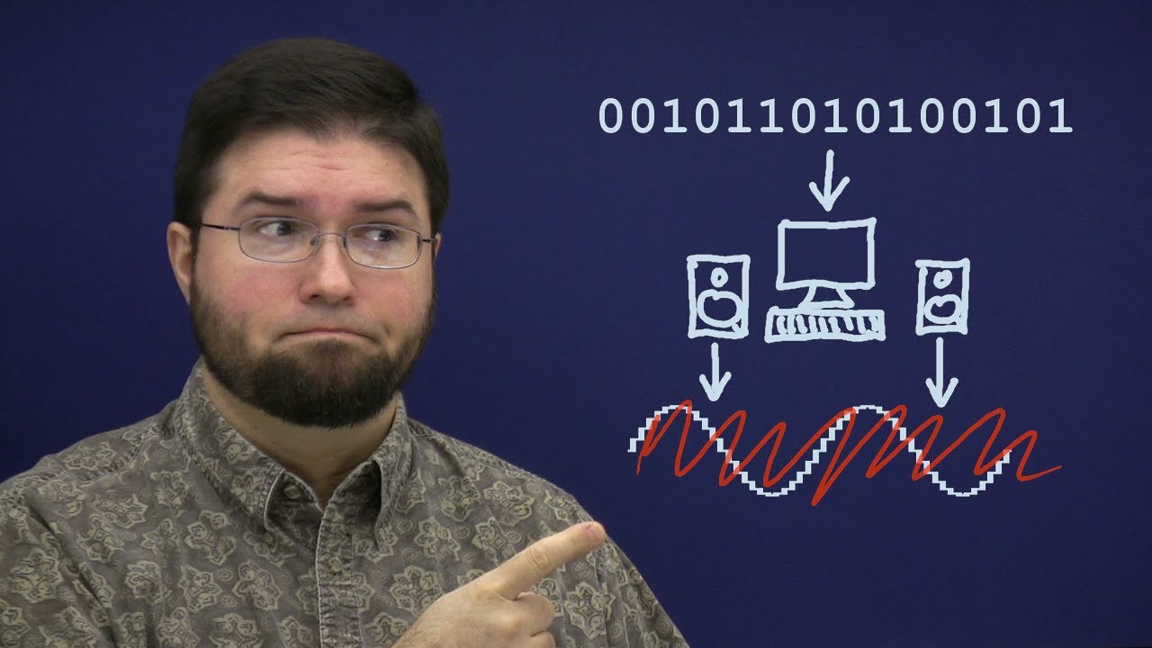
The experiment begins by digitizing the 1 kHz sine wave to 16-bit PCM at 44.1 kHz—identical to standard CD audio format. On the ThinkPad screen, the software visualization renders the digitized sine wave as a classic stair-step pattern, dedicating one horizontal block per sample. Yet when the signal emerges from the D/A converter and appears on the analog output scope, it is an identical, pristine, continuous sine wave with zero stepping.
To test whether the 1 kHz signal is merely so oversampled that steps are too fine to see, Monty increases the generator frequency toward the Nyquist frequency. At 15 kHz, the wave is captured with fewer than three samples per cycle, causing the digital stair-step drawing on the laptop screen to look crude and distorted. On the analog oscilloscope, however, the output remains a clean sine wave. Stepping the frequency up through 16 kHz, 17 kHz, 18 kHz, 19 kHz, and finally to 20 kHz—the absolute upper limit of human hearing—the analog output scope continues to trace an uncorrupted, perfectly smooth sine wave with no level drop-off or jagged edges.
- **Digitization parameters:** 16-bit linear PCM at a 44.1 kHz sample rate. - **Waveform fidelity:** At 20 kHz (fewer than 2.25 samples per cycle), the reconstructed analog output displays zero jaggedness, rounding, or amplitude attenuation.
[05:58](https://www.youtube.com/watch?v=cIQ9IXSUzuM&t=358s) Discrete-Time Sampling vs. Continuous Stair Steps
Monty asks where the stair steps went, revealing it is a trick question: “So where'd the stair steps go? Don't answer; it's a trick question: they were never there.” A stair-step signal is a continuous-time function that maintains an explicit, defined value at every single instant between changes. A digital sampled signal, by contrast, is strictly discrete-time. It possesses values only at instantaneous sample points and is completely undefined at every instant in between. A discrete-time signal is properly represented mathematically as a lollipop graph, not a staircase.
According to the Nyquist-Shannon sampling theorem, when a continuous signal is band-limited to below half the sampling rate (the Nyquist frequency), there is exactly one continuous curve that can pass through all of those discrete sample points. While someone could hand-draw alternative paths connecting the points, any path differing in the slightest degree from the original must incorporate frequencies at or above Nyquist, thereby violating the band-limiting criterion. The original input waveform is the sole valid mathematical solution.
Monty identifies two primary reasons why the stair-step misconception persists: 1. **Zero-Order Hold stages:** Simple digital-to-analog converters often hold an instantaneous voltage level until the next sample arrival as an intermediate step (a zero-order hold). While textbooks and diagrams often show this stepped intermediate stage, it is not a finished conversion and never reaches the final output unchanged. 2. **The "Fat Bits" visualization habit:** Engineers draw stair steps for digital samples much like image editors render pixels as little square boxes ("fat bits"). Pixels are mathematically points sampling a continuous two-dimensional space without volume or shape; rendering them as tiny squares is merely an editing convenience because viewing infinitely small points is impractical.
[08:45](https://www.youtube.com/watch?v=cIQ9IXSUzuM&t=525s) Bit Depth, Quantization, and Tape Hiss
Monty demonstrates that bit depth has no bearing on waveform smoothness. To prove this, he routes the same sine wave through a second channel quantized with dither down to a coarse 8 bits. Observed on the analog oscilloscope, Channel 2 displays a smooth, uninterrupted sine wave rather than a jagged, stepped signal. The only visual difference is the presence of slight trace fuzz, indicating an elevated noise floor.
Quantization affects signal-to-noise ratio rather than signal geometry. Monty explains the distinction: “When we digitize a signal, first we sample it; the sampling step is perfect, it loses nothing. But then we quantize it, and quantization adds noise.” The number of bits determines only the depth of that noise floor.
When Monty isolates Channel 2's noise by applying a notch filter to strip out the fundamental sine wave and raising the monitor gain, the audible result is identical to steady analog tape hiss. When using Gaussian dither, the quantization noise is mathematically equivalent to magnetic tape noise. This equivalence allows the noise floor of magnetic tape formats to be stated directly in bits: - **Standard compact cassettes:** Peak performance reached roughly 9 bits of dynamic range under pristine conditions, but 5 to 6 bits was typical for home consumer decks and mixtapes. - **Professional studio open-reel tape:** State-of-the-art studio reel-to-reel machines using advanced noise reduction systems (such as Dolby SR) barely attained 13 bits of effective resolution. - **The "DDD" CD marker:** The historical "DDD" label on early compact discs was considered an elite audiophile achievement because purely digital recording and mastering bypassed the severe 13-bit ceiling of tape.
[11:39](https://www.youtube.com/watch?v=cIQ9IXSUzuM&t=699s) The Mechanism and Purpose of Dither
Addressing why he specifically refers to quantizing *with dither*, Monty defines the alternative: simple truncation or rounding. In basic quantization, the converter simply selects the nearest discrete digital amplitude level to the incoming analog voltage. While mathematically straightforward, the rounding errors that result correlate directly with the input waveform. This correlation generates harmonically related distortion and unnatural, program-dependent artifacts rather than benign white background noise.
Dither solves this issue by introducing a small, carefully tailored noise signal during quantization. Rather than masking or burying distortion under an added layer of sound, dither randomizes the quantization intervals, completely decoupling quantization error from the input signal. In doing so, it replaces harmonically correlated distortion with an entirely benign, predictable, stationary noise floor of chosen characteristics.
[12:23](https://www.youtube.com/watch?v=cIQ9IXSUzuM&t=743s) Dither: Converting Harmonic Distortion into Linear Noise
Because the analog hardware signal generator introduces too much inherent noise for a delicate quantization test, Monty switches to generating a mathematically synthesized, pristine sine wave on his ThinkPad. Quantizing this pure tone to 8 bits with dither turned on reveals a clean sine wave on both the digital waveform display and the analog oscilloscope. Once the sweeping analog spectrum analyzer catches up, both the digital and vintage analog spectral displays show a sharp, pristine frequency spike resting above a completely uniform, flat noise floor.
```mermaid flowchart TD accTitle: Quantization with and without Dither accDescr: Diagram contrasting how dither converts correlated harmonic distortion into uncorrelated flat noise, and preserves sub-bit signals.
subgraph DitherON["With Dither Enabled"] A1["Quantization to 8 bits"] --> B1["Noise randomized and decorrelated"] B1 --> C1["Flat, uniform noise floor"] C1 --> D1["Signals < 0.5 LSB preserved perfectly"] end
subgraph DitherOFF["Without Dither (Truncation)"] A2["Quantization to 8 bits"] --> B2["Quantization error correlates to signal"] B2 --> C2["Harmonic distortion peaks rise above noise"] C2 --> D2["Signals < 0.5 LSB quantize to absolute zero"] end ```
The moment dithering is switched off, the behavior changes completely. The quantization noise that dither had spread into an innocuous, broadband hiss collapses and concentrates into jagged harmonic distortion spikes. Although the baseline noise floor technically drops lower, the distortion becomes non-zero, with harmonic peaks protruding significantly higher than the dither noise ever reached. At 8 bits, this distortion is visibly prominent, whereas at 16 bits, undithered harmonic distortion drops to levels so low as to be completely inaudible in ordinary listening. As Monty observes regarding audio processing: “Still we can use dither to eliminate it completely if we so choose.”
Dither also completely rescues low-amplitude signals from disappearing. Without dither, the absolute level of quantization distortion remains roughly constant regardless of input amplitude; however, once the signal level drops below half a bit, every sample quantizes to zero, creating total signal loss. As Monty puts it, “In a sense everything quantizing to zero is just 100% distortion.” Re-enabling dither instantly resurrects a tone measuring only one-quarter of a bit, rendering it clearly discernible above the flat noise floor.
- **Test Signal**: Pure sine wave generated mathematically on an IBM ThinkPad, quantized down to 8 bits. - **Spectrum Behavior**: Dither creates a flat, uniform noise floor; turning dither off creates discrete harmonic distortion spikes. - **Sub-bit Performance**: A 0.25-bit (one-quarter LSB) sine wave is completely eliminated by truncation, but fully preserved and recoverable when dither is active.
---
[14:08](https://www.youtube.com/watch?v=cIQ9IXSUzuM&t=848s) Noise Shaping and Dither Power Trade-offs
Because dither is an artificial noise added intentionally, its spectral shape does not have to remain white or flat. Human hearing is acutely sensitive to mid-range frequencies between 2 kHz and 4 kHz, making background hiss in that band particularly intrusive. By employing noise shaping, the energy of the dithering noise is shifted out of the ear's most sensitive mid-range and pushed into the highest audible frequencies where human hearing is far less perceptive. While 16-bit dither noise is ordinarily far too faint to hear, boosting the monitor gain enormously makes the difference obvious, demonstrating how noise shaping effectively vanishes into the background compared to unshaped noise.
Total dithered quantization noise possesses a higher overall root-mean-square power than raw undithered quantization error, which can be seen fluttering on a VU meter during passages of near-silence. Dither is not merely a binary toggle; engineers can reduce dither power to strike a calculated balance between a lower noise floor and minor harmonic distortion. Modulating the amplitude of an input signal demonstrates this interaction: at full dither power, the noise floor remains rock-steady, uniform, and completely uncorrelated with the input signal. As the dither power is dialed back, the modulating input begins to audibly modulate the noise floor itself, producing signal-dependent noise chatter. Noise shaping offers an added benefit here, requiring somewhat less dither power before the input signal begins to audibly modulate the output noise.
Monty steps back to place the entire dither debate into practical engineering perspective. All of these subtle adjustments involve artifacts and noise floors that sit 100 dB or more below full scale. If the Compact Disc standard had frozen at the original 14-bit proposal from early digital development, aggressive dithering would have been vital; at 16 bits, it operates largely as an insurance policy providing a few extra decibels of dynamic range. Monty emphasizes that creative priorities should remain paramount, remarking, “The simple fact is though no one ever ruined a great recording by not dithering the final Master.”
- **Ear Sensitivity Range**: 2 kHz to 4 kHz is the most sensitive band for human hearing, making it the primary region to clear via noise shaping. - **Noise Power vs. Perception**: Shaped dither contains higher total energy than flat truncation noise, yet sounds markedly quieter due to psychoacoustics. - **Dynamic Floor Context**: At 16 bits, dithering effects occur 100 dB below full-scale signal peaks.
---
[17:23](https://www.youtube.com/watch?v=cIQ9IXSUzuM&t=1043s) Square Waves, Band Limiting, and the Gibbs Phenomenon
Moving past simple sine waves, Monty feeds a 1 kHz square wave from the signal generator into the ADC to examine complex waveforms. When viewed on the oscilloscope, the input is a sharp, two-level square wave, but the analog output oscilloscope reveals distinct ripples flanking every sudden level transition. A mathematical square wave is defined as a fundamental frequency summed with an infinite series of odd harmonics. However, real-world digital audio systems do not possess infinite bandwidth; an anti-aliasing filter sharply truncates all energy above 20 kHz.
```mermaid flowchart LR accTitle: Gibbs Effect in Band-Limited Audio accDescr: Flow showing how sharp anti-aliasing removes odd harmonics to create Gibbs ripples, which do not worsen on subsequent filtering passes.
A["Analog 1 kHz Square Wave<br>(Infinite Odd Harmonics)"] --> B["Anti-Aliasing Filter<br>(Cuts off at 20 kHz)"] B --> C["Band-Limited Square Wave<br>(Exhibits Gibbs Ripples)"] C --> D["Second Filter Pass<br>(Same 20 kHz cutoff)"] D --> E["Identical Waveform<br>(Only slight phase/fractional delay)"] ```
Slicing away all harmonics above 20 kHz inevitably transforms the square wave into a band-limited wave containing Gibbs phenomenon ripples around the transitions. A widespread myth asserts that these ripples are nasty distortion artifacts continuously introduced by anti-aliasing and reconstruction filters, implying that each filter pass will compound the ringing. To test this, Monty patches the already-filtered signal through the sharp filter a second time. Outside of introducing a fractional-cycle propagation delay, the waveform does not change at all. As Monty summarizes: “A second pass can't remove frequencies that we already removed.”
Gibbs ripples are not active filter defects; they are the fundamental mathematical definition of a band-limited signal. Even if a user draws a synthetic square wave in digital audio software that appears perfectly rectangular because its transitions line up cleanly with individual sample points, that clean appearance is an illusion created by "connecting the dots." Beneath those samples, the unique band-limited analog signal represented by those points still contains the exact same Gibbs ripples.
- **Harmonic Composition**: A square wave consists strictly of odd harmonics ($f, 3f, 5f, 7f, \dots$) decreasing in amplitude. - **Filter Cutoff**: The ADC's anti-aliasing filter removes all harmonic energy above 20 kHz. - **Gibbs Phenomenon**: Ringing at edges occurs naturally whenever a continuous spectrum is truncated while non-zero energy remains. - **Multi-pass Filter Test**: Sending a band-limited signal through the identical low-pass filter a second time produces zero additional ripple.
---
[20:53](https://www.youtube.com/watch?v=cIQ9IXSUzuM&t=1253s) Timing Precision Between Samples
Another widespread misconception about digital audio is that its timing precision is constrained by the sample period—meaning an event, fast transient, or impulse cannot occur between sample points without being altered or lost. This misconception stems directly from viewing digital audio as stair-steps or discrete connected points rather than instantaneous values of a continuous, band-limited function.
Monty demonstrates that an analog signal's timing is infinitely variable. By shifting the phase of the input square wave, the rising edge can be positioned anywhere between two adjacent sample points. The digital converter does not force the transient onto the nearest sample, nor does the signal disappear or distort. The digital samples faithfully encode the fractional position, and the digital-to-analog converter reconstructs the rising edge at the exact sub-sample timing location with absolute precision. As Monty concludes: “We most certainly can for example put the rising edge of our band limited Square wave anywhere we want between samples it's represented perfectly and it's reconstructed perfectly.”
- **Common Myth**: Digital audio has a timing resolution limited to $1 / \text{sample rate}$ (e.g., $1 / 44,100 \text{ s} \approx 22.7\,\mu\text{s}$). - **Reality**: Because signals are band-limited, sample values encode phase and timing information continuously across sub-sample intervals.
---
[22:05](https://www.youtube.com/watch?v=cIQ9IXSUzuM&t=1325s) Sins of Omission and Resources for Further Hacking
Reflecting on the scope of the demonstrations, Monty acknowledges that covering A/D and D/A conversion, dither, sampling theory, and band-limiting only scratches the surface, admitting humorously that his “sins of omission are greater this time around.” Rather than presenting the video as the final word, he frames it as a launchpad for curious engineers to perform their own experiments. He notes that while the demonstrations were crafted to be straightforward and clear, genuine understanding often comes when you crack a device open to see what falls out.
All source code, including the custom GTK push-button test applications used to drive the demonstrations, is freely published on Xiph.org for anyone wishing to inspect or alter the code. For those encountering unexpected behaviors or seeking deeper theoretical rigor, Monty recommends Wikipedia for casual study, as well as formal university curricula. Specifically, he highlights MIT OpenCourseWare's electrical engineering modules—6.003 and 6.007, focusing on signals and systems—alongside the open-source multimedia community at Xiph.org. Noting that he has finally run out of coffee, he signs off with a cheerful “happy hacking” before the video closes with an outtake musical track.
- **Available Code**: Interactive demonstration software and test utilities are hosted open-source at Xiph.org. - **Academic References**: MIT OpenCourseWare courses 6.003 and 6.007 (Signals and Systems). - **Closing Philosophy**: Hands-on experimentation and breaking systems open is the best path to mastering signal theory.
## Notable quotes > [08:45](https://www.youtube.com/watch?v=cIQ9IXSUzuM&t=525s) When we digitize a signal, first we sample it; the sampling step is perfect, it loses nothing. But then we quantize it, and quantization adds noise. — Monty Montgomery
> [14:08](https://www.youtube.com/watch?v=cIQ9IXSUzuM&t=848s) The simple fact is though no one ever ruined a great recording by not dithering the final Master. — Monty Montgomery
> [02:43](https://www.youtube.com/watch?v=cIQ9IXSUzuM&t=163s) Just because we can measure an improvement doesn't mean we can hear it — Monty Montgomery
## Mentioned Monty Montgomery, Xiph.org, HP 3325, Tektronix 2246, HP 3585, Edirol, IBM ThinkPad, Dolby SR, MIT OpenCourseWare, GTK, FL Studio
## Video description Original Video: http://xiph.org/video/vid2.shtml
Why you don't need 24 Bit 192 kHz listening formats - https://people.xiph.org/~xiphmont/demo/neil-young.html
More videos in this series: http://xiph.org/video/
Get the software - https://wiki.xiph.org/Videos/Digital_Show_and_Tell
Monty at Xiph presents a well thought out and explained, real-time demonstrations of sampling, quantization, bit-depth, and dither on real audio equipment using both modern digital analysis and vintage analog bench equipment.
This video has been reproduced with permission of Monty @ xipg.org and in accordance with Attribution-ShareAlike 3.0 http://creativecommons.org/licenses/by-sa/3.0/
Further reading: Audio Myths & DAW Wars - http://www.image-line.com/support/FLHelp/html/app_audio.htm
This is a video about the digital vs analog audio quality debate. It explains, with examples, why analog audio within the accepted limits of human hearing (20 Hz to 20 kHz) can be reproduced with perfect fidelity using a 44.1 kHz 16 Bit digital signal.
[Source](https://www.youtube.com/watch?v=cIQ9IXSUzuM)