Williams Aztec Pinball Executes Computer Logic Using Cams and Relays
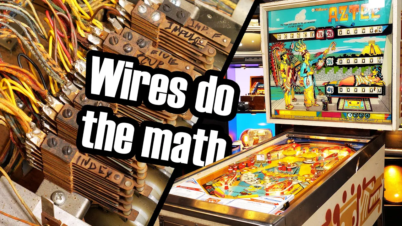
Old pinball machines are amazingly complex — Technology Connections

Technology Connections

Williams achieved dynamic rule sets and variable scoring by routing electrical pulses through motorized cam switches and latching relays decades before microprocessor adoption.

AI-assisted summary of Old pinball machines are amazingly complex — original source. Check the original for full context.

Source published:

Key ideas

  • Williams produced the electromechanical pinball machine Aztec in 1976, orchestrating complex game rules, multiplayer tracking, and bonus logic entirely through relays, stepper units, and switches without microprocessors. (1:50)
  • Score reels create a six-digit scoring illusion using only five physical drum units per player, as Williams screen-printed a static '0' in the units place directly onto the backglass. (10:39)
  • The score motor functions as the electromechanical equivalent of a CPU, using an electric motor, gearbox, and eight profiled cam stacks to generate timed pulse trains and execute complex scoring logic. (28:44)
  • High-wear active mechanisms like pop bumpers and slingshots run on direct current through an under-playfield bridge rectifier, whereas the rest of the machine operates on 24-volt AC power. (23:43)

Detailed notes

## Background Published on YouTube by Technology Connections on October 14, 2023, this video explores the intricate mechanical and electrical design of vintage pinball tables. The description points viewers toward a follow-up second part, shares related channel links and asset attributions, and opens with the classic callout: "Shoot for the magic trunk!"

## TL;DR Using a 1976 Williams Aztec table as a centerpiece, the host explores how pinball machines executed complex game logic and scorekeeping prior to the advent of microprocessors. The breakdown covers the evolution of the medium from parlor bagatelle to modern playfields, examining components like scoring drum reels, chime units, dual-wound flipper coils, and active jet bumpers. Through schematic analysis and physical demonstrations, it reveals how self-holding relay circuits and a multi-cam score motor coordinate timed pulses to carry arithmetic digits, evaluate target hits, and alter playfield states purely through electromechanical hardware.

## Atmosphere & style The presentation is analytical, affectionate, and quietly enthusiastic, driven by the host's clear fascination with physical machines that reveal their inner workings to the naked eye. Pacing is deliberate and educational, balancing rigorous, hands-on mechanical demonstrations with witty, dry observations about the sheer audacity of 1970s wiring looms. Watching it feels like a cozy, late-night workshop masterclass, complete with rhythmic solenoid clatter, glowing incandescent bulbs, and playful outtakes that show the host filming in pajama bottoms.

## Bulletin - [01:50](https://www.youtube.com/watch?v=ue-1JoJQaEg&t=110s) Williams produced the electromechanical pinball machine Aztec in 1976, orchestrating complex game rules, multiplayer tracking, and bonus logic entirely through relays, stepper units, and switches without microprocessors. - [10:39](https://www.youtube.com/watch?v=ue-1JoJQaEg&t=639s) Score reels create a six-digit scoring illusion using only five physical drum units per player, as Williams screen-printed a static '0' in the units place directly onto the backglass. - [28:44](https://www.youtube.com/watch?v=ue-1JoJQaEg&t=1724s) The score motor functions as the electromechanical equivalent of a CPU, using an electric motor, gearbox, and eight profiled cam stacks to generate timed pulse trains and execute complex scoring logic. - [23:43](https://www.youtube.com/watch?v=ue-1JoJQaEg&t=1423s) High-wear active mechanisms like pop bumpers and slingshots run on direct current through an under-playfield bridge rectifier, whereas the rest of the machine operates on 24-volt AC power.

## Key takeaways - [00:06](https://www.youtube.com/watch?v=ue-1JoJQaEg&t=6s) Late-era electromechanical pinball machines like Williams Aztec managed complex multi-player rulesets, scoring ladders, and light sequencing using purely physical and electrical devices instead of microprocessors. - [05:23](https://www.youtube.com/watch?v=ue-1JoJQaEg&t=323s) Modern pinball evolved from 18th-century bagatelle and 1930s tabletop games like Baffle Ball, transforming into a game of timing and skill with the addition of player-controlled flippers in 1947. - [11:42](https://www.youtube.com/watch?v=ue-1JoJQaEg&t=702s) A central cabinet transformer steps wall current down into isolated 24-volt AC circuits for relays and solenoids alongside 6-volt AC circuits for backbox and playfield lamps. - [13:12](https://www.youtube.com/watch?v=ue-1JoJQaEg&t=792s) Relays use self-holding latch circuits wired through end-of-stroke switches to ensure momentary target hits reliably deliver full power strokes to mechanical actuators. - [17:32](https://www.youtube.com/watch?v=ue-1JoJQaEg&t=1052s) Score reels operate as modular, mechanically unlinked units that implement base-10 carryover arithmetic entirely through 9th-position cam switches wired to upstream score relays. - [21:54](https://www.youtube.com/watch?v=ue-1JoJQaEg&t=1314s) Active pop bumpers translate vertical solenoid pulls into forceful horizontal rebounds using a 45-degree beveled metal ring triggered by a floating skirt mechanism. - [25:59](https://www.youtube.com/watch?v=ue-1JoJQaEg&t=1559s) Flipper coils use a dual-winding design with an end-of-stroke switch that shifts current from a low-resistance high-power winding to a high-resistance hold winding to prevent coil burnout. - [28:44](https://www.youtube.com/watch?v=ue-1JoJQaEg&t=1724s) The score motor acts as an electromechanical central processing unit, utilizing an array of rotating cam stacks and leaf switches to generate timed pulse trains. - [32:24](https://www.youtube.com/watch?v=ue-1JoJQaEg&t=1944s) Score motor switches remain electrically inert during normal play until dynamic relay contacts bridge them into active scoring circuits on demand. - [38:00](https://www.youtube.com/watch?v=ue-1JoJQaEg&t=2280s) Relays feature make/break switch assemblies that divert electrical routing between destinations, simultaneously toggling playfield illumination states and multiplying spinner point values. - [43:24](https://www.youtube.com/watch?v=ue-1JoJQaEg&t=2604s) Dynamic scoring targets evaluate lit letters by scanning sequentially closed score motor cam switches against open or closed relay contacts. - [48:08](https://www.youtube.com/watch?v=ue-1JoJQaEg&t=2888s) Electromechanical pinball was not engineered from scratch as a monolithic system, but rather evolved as an iterative accumulation of relay and motor logic across several decades.

## Detailed walkthrough ### [00:06](https://www.youtube.com/watch?v=ue-1JoJQaEg&t=6s) The Wonder of Pinball Machines: Old vs. New

The experience of pinball has captivated players for generations through tactile and kinetic feedback that video screens simply cannot reproduce. The host shares a lifelong fascination with these devices, describing pinball machines as elaborate marvels made by human hands: artists, musicians, designers, voice actors, machinists, and engineers working together to build contraptions meant purely to entertain—and to reliably collect pocket change. Opening up a modern machine like Bally's 1995 *Theatre of Magic* reveals what runs the show: a central computer motherboard. This microcomputer monitors the ball's location across the playfield, updates digital displays, orchestrates digitized speech and sound effects through speakers, and coordinates elaborate lighting choreographies.

Yet less than twenty years before *Theatre of Magic* arrived in arcades, pinball machines contained zero integrated circuits or computer chips whatsoever. The host sets out to explore how an entirely electromechanical machine can replicate complex game logic, scoring, and sequencing using purely physical and electrical devices.

- **Human craftsmanship behind pinball**: Integrates game designers, voice actors, artists, fabricators, and engineers into a single machine. - **Modern pinball control**: Centralized computers track game states, drive audio/video displays, and direct solenoids and lights. - **Historical contrast**: Less than two decades prior to mid-1990s solid-state machines, games operated entirely without silicon logic or digital microprocessors.

```mermaid flowchart LR accTitle: Evolution of Pinball Control Systems accDescr: Diagram contrasting modern microprocessor control with electromechanical relay logic.

subgraph Modern["Modern Pinball (e.g., Theatre of Magic)"] direction TB M1["Microprocessor Motherboard"] --> M2["Digital Displays & Sound Board"] M1 --> M3["Playfield Matrix Switches & Lamps"] end

subgraph EM["Electromechanical Era (e.g., Aztec)"] direction TB E1["Relays & Stepper Units"] --> E2["Mechanical Score Drums & Chimes"] E1 --> E3["Direct Switch Stacks & AC Wiring"] end ```

[01:50](https://www.youtube.com/watch?v=ue-1JoJQaEg&t=110s) Inside Williams Aztec: An Electromechanical Wonder

Williams released *Aztec* in 1976, right at the twilight of the electromechanical (EM) era. While electronics were already on the horizon—Williams actually built ten prototype units of *Aztec* utilizing their experimental System 2 microprocessor platform—the standard production model remains completely electromechanical. Operating the machine produces a distinct, rhythmic mechanical clicking sound in groups of five pulses, prompting a look inside to understand how it operates.

Accessing the machine begins at the backbox. Removing the rear panel does not expose clean circuit boards, but rather “an unholy mess of wires linking quite the assortment of oddball assemblies together.” The main cabinet below holds even more hardware. Gaining entry requires unlocking the coin door, releasing a latching lever that frees the heavy front lockdown bar, removing the bar, sliding out the tempered playfield glass, and lifting the hinged wooden playfield onto its built-in prop rod. Dense arrays of switch stacks, solenoids, and stepper mechanisms sit mounted to both the cabinet floor and the underside of the wooden board itself.

Despite lacking software, *Aztec* manages an intricate ruleset. Players hit specific playfield targets to spell out the letters A, Z, T, E, and C. Completing the sequence lights an extra ball opportunity. Targets advance an end-of-ball bonus ladder up to 50,000 points, which can be multiplied with a double-bonus feature. Maxing out the bonus ladder alongside completing the spelling of AZTEC illuminates a "Special" light to award a free game replay. The machine constantly alternates lit outlanes, awards configurable replay scores, supports three selectable difficulty settings, and accommodates three-ball or five-ball games. It tracks up to four distinct players, cycling turns, disabling flippers when the game ends, and resetting mechanical displays back to zero. Looking at the complex schematic sheet, the host jokes about the sheer density of the engineering:

> “I’m kidding, of course - and even if you studied this for hours, it’s not gonna make any sense unless you understand what these parts are doing and how they work together.”

- **Release date & significance**: *Aztec* was manufactured in 1976 by Williams at the very end of the EM era. - **Prototype electronic run**: Exactly 10 units were fitted with Williams System 2 microprocessor units as developmental testbeds. - **Accessing the cabinet**: 1. Unlock the coin door to access the internal release lever. 2. Pull the lever down to release the front lockdown bar. 3. Lift off the lockdown bar and slide out the tempered playfield glass. 4. Pivot the playfield upward and secure it with the prop rod. - **Game features managed without code**: 1 to 4 players, adjustable 3-ball or 5-ball games, 50,000-point bonus ladders, bonus doubler, alternating lit outlanes, extra ball logic, and replay awards.

[05:23](https://www.youtube.com/watch?v=ue-1JoJQaEg&t=323s) A Brief History: From Bagatelle to Electromechanical Flippers

The term "pinball" traces back to literal pins and balls derived from the 18th-century French parlor game *bagatelle*. Originally, players rolled marbles down an inclined board studded with brass pins that deflected the balls into scored scoring pockets. These parlor games remained manual amusements for the wealthy until the Great Depression, when inventors recognized the potential of coin-operated public entertainment. In 1931, David Gottlieb introduced *Baffle Ball*, widely celebrated as the first commercially successful pinball machine.

Early tabletop games like *Baffle Ball* were purely mechanical and lacked flippers. Inserting a coin and pushing the mechanical coin slide opened internal trapdoors, dropping trapped marbles down to a lower trough where a manual plunger could launch them onto the playfield. Players tallied scores by hand, and the games quickly spread across bars, drugstores, and speakeasies nationwide—often accompanied by informal gambling. The runaway success of *Baffle Ball* sparked competitive imitators, most notably *Ballyhoo*, a game so profitable that its manufacturer adopted its name, becoming the Bally Manufacturing Corporation.

To outdo each other, competing amusement companies rushed to invent novel electrical and physical features, introducing electrically lit bulbs, scoring bells, dynamic bumpers, and automatic scorekeeping. The definitive leap forward came in 1947 when D. Gottlieb & Company released *Humpty Dumpty*, the first game equipped with player-controlled electromechanical flippers. Although *Humpty Dumpty* featured six flippers mounted facing outward along the sides of the playfield, it established the core mechanics that defined the industry for decades, culminating in late-era electromechanical titles like Williams' *Aztec* 29 years later.

- **18th Century origin**: Derived from *bagatelle*, an inclined wooden board using pins to deflect rolling marbles into scoring cups. - **David Gottlieb (1931)**: Invented *Baffle Ball*, introducing a coin slide mechanism that mechanically cleared trapped balls for replay. - **Ballyhoo (1932)**: Manufactured by Raymond Maloney; its extraordinary success caused the company to rename itself Bally. - **Electromechanical flipper introduction (1947)**: Gottlieb’s *Humpty Dumpty* debuted player-controlled flipper bats, forever changing pinball from a game of chance to a game of timing and skill.

[08:00](https://www.youtube.com/watch?v=ue-1JoJQaEg&t=480s) Anatomy of the Aztec Playfield

At its foundation, the modern pinball playfield is a smooth wooden board set at a downward incline, flanked on the right by a dedicated shooter lane. A spring-loaded, player-operated manual plunger launches the steel ball into orbit toward the top of the board. A graduated gauge printed behind the shooter spring allows players to meter their release strength with precision, an essential mechanic for machines that incorporate a designated "skill shot" to award extra points right off the launch.

The open areas of the board are divided by physical obstacles that guide the ball's trajectory. These boundaries consist of plastic posts screwed directly into the playfield, wrapped with resilient rubber rings. Rings stretched between adjacent posts form linear rebound walls, sending balls ricocheting across the wood and occasionally tripping underlying leaf switches worth 10 points. To protect the underlying electrical components, decorative screen-printed plastics sit atop the posts, matching the visual theme of the cabinet while safely sheltering incandescent playfield illumination bulbs from high-velocity ball strikes.

*Aztec* combines a balanced assortment of mechanical playfield mechanisms to award points and activate game rules:

- **Rollover buttons**: Three small plastic discs set flush into the wood, depressed as the ball rolls over them. - **Rollover lanes**: Eight wire-form gate triggers spanning designated ball channels. - **Stand-up targets**: Six upright plastic targets that close internal electrical leaf switches when struck head-on. - **Spinning target**: One rotatable metal target suspended on a wire axle, spinning rapidly to rack up points with each revolution. - **Kickback lane**: One isolated return lane designed to propel the ball back into active play. - **Slingshot kickers**: Two triangular electromechanical rebound arms situated just above the flippers. - **Jet Bumpers**: Three high-powered active pop bumpers (branded by Williams as "Jet Bumpers" for trademark purposes) that fire a solenoid ring downward whenever their perimeter skirts are nudged.

[10:39](https://www.youtube.com/watch?v=ue-1JoJQaEg&t=639s) The Backglass and the Fake-Digit Scoring Illusion

Scores are presented on the illuminated backglass inside the backbox head unit via mechanical rotary drums known as score reels. While looking at the backglass of an electromechanical machine like *Aztec*, players see what appears to be a six-digit score display for each of the four possible players. However, opening the back of the backbox reveals an amusing manufacturing secret: there are only five functional score reels installed per player.

The final digit on the far right of every score display—the ones position—is completely fake. The "0" digit is simply screen-printed directly onto the glass to visually inflate player scores by a factor of ten, turning a 1,000-point play into an impressive 10,000-point display. To preserve the illusion and prevent the printed zero from looking out of place alongside real mechanical tumblers, Williams cleverly printed the very bottom edge of a "9" and the very top edge of a "1" above and below the dummy zero, perfectly mimicking the visible edges of the physical drum reels adjacent to it.

Beneath the glass, the actual scoring work relies on Williams' individual "drum units." Each unit consists of a molded plastic reel numbered 0 through 9 around its perimeter, advanced one step at a time through a solenoid coil, an armature, and a mechanical drive pawl.

- **The dummy zero illusion**: Scores show six digits on the backglass, but only five physical drum units exist in the backbox per player; the units position is permanently painted onto the glass. - **Visual detail**: Williams printed faint portions of a 9 and a 1 above and below the painted zero so the stationary digit matches the physical reels beside it. - **Drum unit assembly**: Each Williams score drum is an electromechanical module combining an actuating solenoid, drive linkage, and rotary number cylinder.

[11:42](https://www.youtube.com/watch?v=ue-1JoJQaEg&t=702s) Electromagnets, Power Delivery, and the Chime Unit

The heart of an electromechanical score display is a ratcheting mechanism designed to advance a numbered drum by exactly one-tenth of a full rotation per pulse. This motion is driven by a small solenoid—a type of electromagnet—that pulls on a plunger whenever current flows through its coil. Technology Connections quips about the machine's heavy reliance on electromagnetic actuators: “By the way, I hope you like electromagnets ‘cause this machine is chock full of ‘em.” Power for the entire game is supplied by a massive transformer mounted in the bottom of the cabinet. This transformer steps wall voltage down to 24 volts AC for the game circuitry and solenoids, alongside a secondary 6-volt AC tap used for all the playfield and backbox illumination lamps.

All playfield scoring targets are fundamentally simple mechanical switches that become connected into the active scoring circuitry once a game is started. For instance, the 100-point rollover buttons on the playfield are physical plastic buttons resting above a pair of flexible electrical contacts. When the mass of the pinball presses the button downward, the contacts close. Rather than directly energizing the score reel solenoid alone, pressing this switch simultaneously fires an auditory indicator: the chime unit. Located in the main cabinet near the coin door, the chime unit contains three tuned metal chime bars, each paired with its own dedicated solenoid positioned directly beneath it. Energizing a chime coil shoots a plunger violently upward to strike the underside of the chime bar, producing a bright metallic ring reminiscent of the iconic three-note NBC chimes.

- The cabinet transformer converts line voltage to 24 V AC (logic and solenoids) and 6 V AC (general and feature lighting). - Scoring switches are passive contacts wired into the circuit only while the game is on and in play. - The chime unit houses three separate bars and solenoids, providing distinct acoustic pitch feedback for different scoring point values.

---

[13:12](https://www.youtube.com/watch?v=ue-1JoJQaEg&t=792s) Relays, Arcing, and Self-Holding Latch Circuits

Because registering a single 100-point hit requires simultaneously firing two separate, high-current solenoids placed far apart from one another—the score reel drum up inside the backbox and the chime unit down inside the lower cabinet—the small switch on the playfield cannot handle the load directly. Instead, closing the playfield button energizes the 100-point relay located in the backbox. When current passes through the relay coil, its magnetic field pulls an armature plate that physically actuates a stack of switch blades. While relays in some industrial applications are straightforward, Technology Connections stresses that pinball logic pushes them to extremes: “Pinball pushes relays to their conceptual limit using them to create the game logic and do countless other tasks, but that’s a big part of why I like these machines so much.”

A single relay can host various configurations of switch leaves: normally open (NO), normally closed (NC), and make/break switches. On the 100-point relay, hitting any 100-point target closes contacts to energize both the hundreds score drum solenoid and the small chime solenoid in parallel. Routing this current through relay-grade contact points protects the delicate playfield switches from the heavy electrical arcing generated by collapsing inductive solenoid fields.

```mermaid flowchart TD accTitle: Score Relay Latch and End-of-Stroke Break Circuit accDescr: Shows how a playfield switch triggers the score relay, which locks itself on until the score reel's end-of-stroke switch opens.

subgraph Trigger ["Playfield Input"] SW["100-Point Target Switch"] end

subgraph RelayHold ["100-Point Relay (Backbox)"] R_Coil["Relay Coil"] R_Hold["Relay Self-Hold Switch (NO)"] R_Chime["Chime Switch (NO)"] R_Reel["Reel Drive Switch (NO)"] end

subgraph Actuators ["Outputs & Feedback"] Chime["Chime Solenoid"] Drum["Score Reel Solenoid"] EOS["End-of-Stroke Switch (NC)"] end

SW -->|"momentary pulse"| R_Coil R_Coil --> R_Hold R_Coil --> R_Chime R_Coil --> R_Reel R_Chime --> Chime R_Reel --> Drum Drum -->|"plunger reaches travel limit"| EOS R_Hold -->|"latching loop"| EOS EOS -->|"breaks holding circuit"| R_Coil ```

Beyond triggering outputs, the 100-point relay contains six distinct switches to solve mechanical timing issues. Solenoids require a finite amount of time to pull a plunger completely through its stroke. If a fast-moving ball merely grazes a target, the momentary closure would not supply current long enough for the score drum to index a full step. To prevent partial steps, one of the relay's internal normally open contacts acts as a lock-in (self-holding) switch. Once energized, this contact closes and feeds current back into the relay's own coil, keeping the relay pulled in independently of the playfield target. To prevent the coil from locking on permanently, the self-hold circuit is wired in series through a normally closed end-of-stroke (EOS) switch mounted directly on the score reel frame. Only when the score reel solenoid plunger reaches the absolute end of its mechanical stroke does it push open the EOS switch, cutting power to the relay coil and releasing the mechanism.

- The 100-point relay features six switch blades handling triggering, chime actuation, holding logic, and carryover. - Self-holding circuits guarantee that fleeting ball impacts still provide a full, complete stroke to electro-mechanical actuators. - On schematic diagrams, electrical current paths run horizontally across the sheet between AC rails, with targets wired in parallel and safety/EOS switches wired in series.

---

[17:32](https://www.youtube.com/watch?v=ue-1JoJQaEg&t=1052s) The 9th-Position Switch and Decimal Carry Logic

The score reels operate as entirely modular, mechanically independent units; there is no mechanical odometer gearing tying the tens, hundreds, thousands, or tens-of-thousands drums together. To handle standard base-10 arithmetic, the machine uses electrical interlocks to carry the one. Technology Connections points out the necessity of this design: “The score reels are not mechanically linked - each one operates entirely independently of the others.” When a player sitting at 900 points hits a 100-point target, the display must advance the hundreds drum from 9 to 0 while simultaneously advancing the thousands drum from 0 to 1.

This carryover is coordinated by a switch stack mounted near the top of each score reel mechanism. A pivoting cam arm rides the reel drum and drops into a specialized profile only when the drum rotates into the 9 position, closing a normally open "9th-position" switch. This switch is wired directly to an extra set of contacts on the 100-point relay. When the active player's hundreds reel is resting on 9 and another 100-point score is scored, current passes through the 100-point relay contacts, flows across the closed 9th-position switch, and energizes the 1,000-point relay coil at the same time. Both relays pull in together, causing both the hundreds and thousands score drums to increment alongside their corresponding chimes. Because every digit reel incorporates this exact electrical handoff, an unbroken chain of carries functions seamlessly: hitting a single 10-point switch when the machine sits at 99,990 will trigger a cascade across five relays and reels, rolling the entire display over to 100,000 points with an emphatic, simultaneous clatter of solenoids and chimes.

---

[19:28](https://www.youtube.com/watch?v=ue-1JoJQaEg&t=1168s) Passive Playfield Targets: Rubbers, Stand-Ups, Rollovers, and Spinners

The playfield populates its scoring grid using a variety of passive electromechanical target styles. The simplest form consists of contact leaf switches tucked directly behind the white rubber rings stretched across structural posts. When a ball impacts the rubber band, the deflection pushes the leaf contacts together, energizing the 10-point relay, dinging the bell, and stepping the machine's internal number-match unit. Stand-up targets work on an identical principle, but feature an upright plastic target face fixed directly to one of the switch blades. Calibrating the air gap on stand-up leaves is crucial: if the contact gap is adjusted too wide, hard hits fail to register, but if spaced too close together, ambient vibrations from nearby ball bounces can trigger phantom scores.

```mermaid flowchart LR accTitle: Target Switch Varieties and Activation Methods accDescr: Classifies four passive target types by how ball interaction is translated into contact closure.

subgraph Direct ["Direct Deflection Targets"] Rubber["Rubber Ring Bumper"] -->|"ball flexes rubber"| Leaf1["Rear Leaf Switch"] StandUp["Stand-up Target"] -->|"ball strikes plastic face"| Leaf2["Integrated Leaf Switch"] end

subgraph Mechanical ["Linkage-Actuated Targets"] Rollover["Rollover Lane / Button"] -->|"ball depresses wire / button"| Leaf3["Sub-playfield Contacts"] Spinner["Spinning Target"] -->|"ball rotates eccentric axle"| Leaf4["Pulsing Leaf Linkage"] end ```

Rollover lanes rely on shaped trip wires extending upward through precision slots cut into the wood playfield, pressing leaf contacts beneath the board when depressed by the ball's weight. While typical rollover lanes allow bidirectional actuation, designers occasionally implement one-way gates or directional trip wires. The outlanes in the Aztec table feature one-way wire profiles bent to yield exclusively when the ball rolls downward toward the drain. If an erratic bounce off the lower apron propels the ball upward into the outlane, the ball hits the rigid backside of the wire and drops back down into the trough.

The spinning target uses a freely rotating metal plate mounted on an eccentric wire axle. As the ball blasts through the spinner, the eccentric bend translates rotational inertia into rapid up-and-down oscillations via a vertical wire linkage extending through a hole in the playfield. This linkage pulls against a leaf switch, making and breaking contact with every revolution to rack up rapid-fire points and chimes.

- Contact gaps on leaf switches dictate the mechanical sensitivity and force threshold required to register a valid hit. - Aztec outlane trip-wires are mechanically biased downward, preventing upwardly rebounded balls from escaping the drain. - Spinning targets transform rotary motion into reciprocating linear motion to pulse a single score relay repeatedly.

---

[21:54](https://www.youtube.com/watch?v=ue-1JoJQaEg&t=1314s) Williams Jet Bumpers and Active Ball Repulsion

Active playfield targets differ from passive switches by actively projecting the ball away with high kinetic force. Foremost among these are jet bumpers (frequently called pop bumpers), which Williams pioneered in 1948. A jet bumper is triggered by a floating circular plastic ring called the skirt, which sits flush with the playfield surface and connects to a downward-pointing rod seated in a conical cup mechanism beneath the board. Regardless of the angle from which a ball strikes the skirt, the tilting action pushes the center pin outward, forcing the cup downward to close a sensitive leaf switch.

Closing this switch immediately supplies high-current power to a powerful solenoid positioned directly under the bumper assembly. The solenoid plunger draws downward, pulling a spring-loaded metal ring suspended above the skirt violently toward the playfield. Because the inner rim of this ring is beveled at roughly a 45-degree angle, its rapid downward stroke strikes the top curvature of the pinball while the ball is wedged against the skirt, violently firing it outward across the board. The mechanical shock is so extreme that modern restorations install clear Mylar protective rings around the bumper bases to prevent the metal ring and ball impacts from destroying the wood playfield over time—a protective measure that was not standard when these machines were manufactured. To register scoring, jet bumpers either incorporate a secondary switch actuated at the bottom of the solenoid bracket's travel, or employ an auxiliary pop bumper relay that latches on to pulse the scoring drums and chimes.

- Williams introduced the jet bumper design in 1948, transforming bumpers from passive rebound posts into active solenoid-driven slings. - The 45-degree beveled metal ring strikes the upper hemisphere of the trapped 1-1/16 inch steel ball, translating vertical solenoid pull into horizontal ball velocity. - The severe downward force of pop bumper rings frequently caused playfield paint and wood wear on classic machines lacking protective Mylar rings. - Point scoring from a jet bumper is decoupled from the skirt trigger, using either a dedicated travel switch beneath the bumper or an auxiliary latching relay.

[23:43](https://www.youtube.com/watch?v=ue-1JoJQaEg&t=1423s) Pop Bumpers, Slingshots, and Kickbacks

Different pinball manufacturers tackled pop bumper activation in slightly different ways. While some designs use an end-of-stroke switch to release a relay after the bumper fires, Williams opted to power the solenoid directly from the bumper's skirt switch. As the host points out, “The main downside of this approach is that occasionally the ball will just brush against the bumper, so it kinda-sorta half-fires and it doesn’t award points.” Down below, flanking the flippers, sit the slingshots. Described as “dastardly things,” they are hardly worth hitting deliberately because they award a meager 10 points while possessing “a nasty habit of flinging the ball right into the outlanes.” Mechanically, a slingshot consists of three posts arranged in a triangle surrounded by a large rubber ring. Behind the long edge sits a kicker flanked by two switch contacts. When a ball impacts the rubber, closing either switch, an under-playfield solenoid fires, thrusting the kicker outward, stretching the rubber ring, and launching the ball away. As with the pop bumpers, the switches behind the rubber solely trigger the coil, while a secondary switch mounted underneath actually registers the score.

Near the slingshots rests the kickback lane, which functions as an ingenious hybrid of a slingshot kicker and a rollover lane. When a ball rolls down the lane, it depresses a trip wire that triggers scoring, immediately followed by an under-playfield solenoid that fires and bonks the ball straight back up into the active playfield. An unexpected technological detail lurks beneath the surface of the Aztec machine: both the pop bumpers and the slingshot solenoids run on direct current rather than alternating current.

Williams mounted a bridge rectifier and a filtering capacitor to the underside of the wood playfield, introducing solid-state electronics to an otherwise electro-mechanical machine. As the narrator quips, this setup “means that there is in fact a single semiconductor in this machine! Or four depending on how you wanna define things.” DC-driven solenoids generate noticeably more punch than AC coils, prompting Williams to experiment with them during this manufacturing era. Aside from the pop bumpers and slingshots, every other component in the cabinet—including the flippers—operates on standard 24 volts AC.

- **Slingshot Structure:** Three posts in a triangular configuration enclosed by a rubber ring, with two leaf switches flanking an internal mechanical kicker. - **Scoring Value:** Slingshots score only 10 points each. - **Power Architecture:** Solenoids for pop bumpers and slingshots use rectified DC power for snappier actuation; the rest of the machine operates on 24V AC. - **Semiconductor Count:** A single bridge rectifier component (internally containing four diodes) mounted beneath the playfield.

---

[25:59](https://www.youtube.com/watch?v=ue-1JoJQaEg&t=1559s) Flipper Solenoids and End-of-Stroke Switches

Like almost every moving mechanism in the cabinet, the flippers rely on solenoids, but their player-controlled nature presents a distinct engineering hurdle. Pressing the exterior cabinet buttons pushes leaf switch contacts together, sending power to the flipper coils to pull a mechanical linkage and snap the flipper bat upward. However, while most game solenoids fire in short, transient pulses, players frequently cradle the ball by holding the flipper button down. A powerful solenoid sustained under high continuous current generates rapid heat, meaning “coils that overheat tend to get melty, then smoky, and on rare occasions, firy.” While slow-blow fuses protect the cabinet from a catastrophic fire if a coil locks on, the flippers must remain elevated safely for extended periods without melting.

To solve this, Williams utilized specialized dual-wound coils with three electrical terminals. The long coil of continuous wire features a center tap that effectively divides it into high-power and low-power stages:

```mermaid flowchart TD accTitle: Flipper Coil Power Circuit accDescr: Circuit path showing initial high-power stroke switching to low-power holding circuit via EOS switch.

subgraph RestState["Rest Position (Button Pressed)"] A["Cabinet Button Closes"] --> B["Power routed to Center Tap"] B --> C["Current bypasses half of coil turns"] C --> D["High Current / Maximum Stroke Power"] end

subgraph FullStroke["Full Stroke Reached"] D --> E["Flipper linkage opens EOS switch"] E --> F["Center tap disconnected"] F --> G["Current travels through entire coil length"] G --> H["Low Current / Sustained Hold Power"] end ```

When the flipper bat is resting and the player first hits the button, current flows directly into the center tap. By bypassing half of the total windings, the electrical resistance is halved and current increases dramatically, producing the high magnetic punch required to flip a heavy steel ball. The moment the flipper linkage reaches the end of its stroke, it physically pushes open an end-of-stroke (EOS) leaf switch. Opening this switch cuts off the center tap, forcing the current to pass through the full resistance of the entire coil winding. This drop in current produces just enough magnetic pull to hold the bat up while preventing the coil from burning up. The host vividly demonstrates this behavior by manually overpowering the raised flipper bat with his fingers while holding the cabinet button; the machine hum shifts from a quiet buzz to a ferocious, loud rattle, visibly dimming the cabinet playfield lights from the massive current draw.

---

[28:44](https://www.youtube.com/watch?v=ue-1JoJQaEg&t=1724s) The Ubiquitous Number Five and the Score Motor

Beneath its flashy lights, the game relies on complex layers of physical logic built atop primitive scoring mechanisms. The machine must count down the player's allotted three balls per game, track which player is up, index the active score reels across multiplayer matches, and ignore ball advance cycles whenever an extra ball is earned. Central to this logic is the recurring appearance of the number five. The bonus ladder begins at 5,000 points and increments in steps of 5,000; the stand-up target awards 500 points; certain lanes and kickbacks deliver 5,000 points; and the title theme itself, "AZTEC," consists of five letters whose lit values scale point awards.

When a 5,000-point switch is hit once, the score reel clicks forward five times in steady rhythmic quintuplets. This automated cadence is produced by the "score motor"—a device the narrator describes by stating: “This wonky looking contraption is the closest thing this machine has to a central processing unit.” The score motor consists of a small electric motor coupled to a speed-reduction gearbox that rotates a drive shaft bearing eight distinct cams, each operating a tall stack of leaf switches.

``` [ Cam Stack Arrangement: Left to Right ] (Index) (1) (2) (3) (4) (5) (Impulse) (Impulse Forward) ```

The cam stacks perform distinct mechanical timing functions: - **Index Cam:** Located on the far left; features the critical Motor Run switch on the top of its stack. - **Cams 1 through 5:** Staggered cutouts or bumps that actuate switches in a sequential 1-2-3-4-5 rhythm. - **Impulse & Impulse Forward Cams:** Outfitted with five distinct teeth that pulse their switch stacks five times during each rotational cycle. The Impulse Forward stack contains a single switch dedicated exclusively to the machine reset cycle.

On the index cam, the Motor Run switch acts as a self-holding circuit analogous to relay interlocks. Once any game event nudges the score motor away from its resting home position, the Motor Run switch rides out of its notch and closes, feeding continuous power to the motor until the cams rotate through an entire operational cycle and drop back into the home detent. Yet, manually nudging the cam shaft to trigger a rotation produces a clattering burst of switches without changing the score. As the host explains, almost all switches on the score motor sit on isolated open circuits during normal play; the machine only performs work by using relays to dynamically rewire these revolving switch contacts to other circuits on the fly.

---

[33:47](https://www.youtube.com/watch?v=ue-1JoJQaEg&t=2027s) Executing the 5,000-Point Sequence

To illustrate how relays harness the score motor, the host traces the activation path of a 5,000-point rollover switch. Hitting the rollover wire does not connect directly to the scoring reels or bells; instead, it energizes the 5,000-point relay mounted under the playfield. This relay contains three sets of switch contacts that bridge into the score motor:

1. **Motor Start Switch:** Bridges contacts to supply initial power to the score motor, starting its rotation so the index cam can engage the Motor Run interlock. 2. **Relay Interlock Switch:** Closes to form a latching circuit that keeps the 5,000-point relay energized after the pinball has rolled off the lane trip wire. 3. **Scoring Pulse Switch:** Bridges the 1,000-point relay in the backbox directly to the cycling switch stack on the score motor's impulse cam.

To make the sequence clear, the narrator physically unplugs the score motor to freeze it midway. With the motor stopped, the 5,000-point relay remains locked on, unable to clear its state because the mechanical cycle cannot finish. When power is restored to the motor, the impulse cam spins past its switch stack, pulsing the closed circuit to the backbox 1,000-point relay exactly five times in rapid succession, chiming the bell and stepping the 1,000s reel forward five positions.

Just as the fifth pulse finishes firing, the self-holding interlock on the 5,000-point relay hits a normally-closed leaf switch located on cam stack 5 of the score motor. As cam five reaches its cutout, it pushes that switch open, severing the relay's holding power. The 5,000-point relay drops out, the score motor notches into its index home position, the Motor Run switch drops into its park detent, and the machine returns to its resting state.

[35:56](https://www.youtube.com/watch?v=ue-1JoJQaEg&t=2156s) Hand-Cranking the Score Motor: The 5,000-Point Timing Sequence

To demonstrate the exacting mechanical precision inside the Aztec machine, the host turns the score motor slowly by hand rather than letting it fire at full operational speed. Because the entire sequence usually resolves in a fraction of a second, manual rotation lets viewers see and hear every individual contact event: the loud mechanical dings, the buzzing, and the solid clunks of solenoids pulling in. The cycle begins when the 5,000-point relay energizes and immediately locks itself on through a dedicated switch riding on cam 5. At the same time, this relay connects the score motor's impulse switch directly through to the 1,000-point score reel relay.

As the score motor rotates through its stroke, the impulse switch stack rides over five successive lobes, pulsing the 1,000-point relay five distinct times to ring up the score. Throughout these five pulses, the 5,000-point relay remains firmly locked on. Only when the fifth impulse has finished does the switch stack on cam 5 fall into its cut divot, opening the circuit, cutting power, and letting the relay drop with a sharp mechanical click.

The mechanical synchronization between these separate cam profiles is remarkably tight. As the host notes, “As you can imagine, the timing here is critical and the cams are aligned so that the fifth bump of the impulse switch happens just before cam 5 actuates its switches (which also happens just before we get back to the start point and the index switch actuates).” Once electric power is restored to the motor, this intricate mechanical choreography plays out automatically in a split second. Reflecting on the sheer physical ingenuity, the host remarks, “I hope you can appreciate how amazingly bonkers this is.” Yet this intricate dance represents merely one of the machine's simplest relays performing one of its most basic automated tasks.

```mermaid flowchart TD accTitle: 5000 Point Motor Timing Cycle accDescr: Sequence diagram illustrating how the score motor and cam switches cycle through 5000 points.

subgraph Trigger["Initiation"] A["Target Hit"] --> B["5,000-Point Relay Energizes"] B --> C["Relay Locks On via Cam 5 Switch"] B --> D["Impulse Switch Connected to 1,000-Point Relay"] end

subgraph Cycling["Cam Rotation"] D --> E["Impulse Cam Pulses Switch 5 Times"] E --> F["1,000-Point Reel Advances 5 Times (5,000 Pts)"] end

subgraph Reset["Sequence Completion"] F --> G["Cam 5 Stack Drops into Divot"] G --> H["5,000-Pt Relay Drops Out"] H --> I["Index Switch Reached; Motor Halts"] end ```

[38:00](https://www.youtube.com/watch?v=ue-1JoJQaEg&t=2280s) The AZTEC Letter Relays and Make/Break Switches

With over thirty additional switches on the score motor and scores of relays still unaddressed, the machine holds far more logic than can fit into a single video, necessitating an upcoming second installment. Turning to the five standalone letter targets—A, Z, T, E, and C—the host highlights that striking each target energizes a corresponding relay. In a nod to service technician ergonomics, Williams mounted these relays side by side in neat alphabetical order on a wooden structural rail beneath the playfield.

Focusing in detail on the A relay reveals that this single unit contains three distinct contact blade arrangements: - **Normally Open (NO):** The three leftmost blade pairs remain separated at rest; when the relay coil energizes and pulls its armature plate, these contacts push together to close circuits. - **Normally Closed (NC):** The next switch maintains continuity at rest and opens to sever a circuit when the relay pulls in. - **Make/Break (Form C):** The two rightmost blade assemblies use a moving center blade that disconnects from one stationary outer blade and transfers to another, steering an electrical path between two destinations rather than simply toggling power on or off.

When the A rollover lane is struck, power triggers the A relay, which immediately closes its leftmost normally open switch to create a hold circuit. As the host explains, “And this relay will stay locked on until the end of the ball-in-play.”

The make/break switches on the relay radically alter both the playfield's visual state and its scoring behavior. The first make/break switch manages illumination. Before the target is struck, 6 volts AC passes through the normally closed side to light the "Lites A" lane insert. Once the A relay trips and locks on, that light extinguishes as power is switched over to illuminate the two "A" inserts on the playfield alongside the spinning target.

Concurrently, the second make/break switch switches the value of the spinner from 100 points to 1,000 points per rotation. Tracing the physical wiring harness demonstrates this hardware logic: - The spinner switch connects to a gray wire with a red stripe (`gray/red`). - This wire enters the wiring harness and travels directly to the A relay's center blade. - At rest, current routes through the NC contact out a white wire with a red trace (`white/red`) routed up through a Jones plug to the backbox's 100-point relay coil. - Once energized, the center blade shifts against the NO contact, routing the pulse along a brown wire with a yellow trace (`brown/yellow`) up to the backbox's 1,000-point relay coil.

[41:32](https://www.youtube.com/watch?v=ue-1JoJQaEg&t=2492s) The Center Target: Dynamic Series Logic

The A relay modifies far more than just the spinner; it also works alongside the other four letter relays to dictate the values of the center target and the kickback lane (labeled as the "shooter" on the factory schematics). Both of these field features scale dynamically: when no letters are lit, they award a fixed base score, but once any letters are lit, they award points for *each* individual letter collected. For the center target, that means 1,000 points per lit letter; the kickback lane awards 10,000 points per lit letter. Each target can evaluate to six distinct scoring values (from zero up to five letters lit).

Achieving this variable scoring without a microcontroller is handled by two parallel circuit paths. Hitting the center target energizes the center target relay, which locks itself on, starts the score motor, and ties the impulse switch to the score reels.

If no letters in AZTEC have been collected: - Power from the impulse switch follows a gray-and-white wire on the schematic to coordinate B-19. - It encounters a daisy chain of five normally closed switches wired in pure series—one across each of the A, Z, T, E, and C relays. - Because all five letter relays are resting unenergized, this series chain remains unbroken. - The five pulses from the score motor's impulse switch route straight through to the 100-point relay, awarding 500 points. - If even a single letter has been struck, however, its respective relay pulls in, opening its NC contact and breaking this series path entirely, silencing the 500-point payout.

```mermaid flowchart LR accTitle: Base 500-Point Series Interruption Circuit accDescr: Circuit path showing how five normally closed relay contacts in series must all remain closed to pass 500 points.

A["Impulse Switch (5 Pulses)"] --> B["A Relay (NC)"] B --> C["Z Relay (NC)"] C --> D["T Relay (NC)"] D --> E["E Relay (NC)"] E --> F["C Relay (NC)"] F --> G["100-Point Relay Coil (500 Pts Total)"]

style G stroke:#2b822b,stroke-width:2px ```

[43:24](https://www.youtube.com/watch?v=ue-1JoJQaEg&t=2604s) The Score Motor Scanning Sequence

When letters *are* lit, the machine calculates the boosted score through an electromechanical scanning sequence. On the Williams schematic, a bank of five normally open switches on the A, Z, T, E, and C relays sits beneath five distinct circles indicating contacts actuated by cams on the score motor: - **A Relay Switch:** Paired with the score motor's Index stack, switch B (`Index-B`, the second switch from the bottom). - **Z Relay Switch:** Paired with cam stack 1, switch A (`1-A`, bottom switch). - **T Relay Switch:** Paired with cam stack 2, switch A (`2-A`). - **E Relay Switch:** Paired with cam stack 3, switch A (`3-A`). - **C Relay Switch:** Paired with cam stack 4, switch A (`4-A`).

Because the score motor's cam lobes are physically staggered around the central shaft, these switch stacks close sequentially, one after another, as the motor revolves. The host describes this process: “So you can imagine what’s happening here as a sort of scanning sequence.”

```mermaid flowchart TD accTitle: Score Motor AZTEC Letter Scanning Sequence accDescr: Flow diagram showing how sequentially actuated score motor cam switches pulse letter relays into the 1,000-point coil.

subgraph MotorCams["Sequential Motor Cams"] M0["Index Cam (Stack B)"] M1["Cam 1 (Stack A)"] M2["Cam 2 (Stack A)"] M3["Cam 3 (Stack A)"] M4["Cam 4 (Stack A)"] end

subgraph Relays["AZTEC Relay NO Switches"] R0{"A Relay Closed?"} R1{"Z Relay Closed?"} R2{"T Relay Closed?"} R3{"E Relay Closed?"} R4{"C Relay Closed?"} end

subgraph Output["Chime & Reel Action"] Out["1,000-Point Relay Coil (+1,000 pts per closed letter)"] end

M0 -->|Pulse 1| R0 M1 -->|Pulse 2| R1 M2 -->|Pulse 3| R2 M3 -->|Pulse 4| R3 M4 -->|Pulse 5| R4

R0 -->|Yes| Out R1 -->|Yes| Out R2 -->|Yes| Out R3 -->|Yes| Out R4 -->|Yes| Out ```

When the center target relay pulls in, it connects the output of these scanning circuits to the 1,000-point relay coil. The Index-B switch fires its pulse immediately. As the motor continues its rotation, that switch opens and cams 1, 2, 3, and 4 fire their pulses down the line. If a given letter's relay is energized, its normally open contact is closed, allowing that specific cam's pulse to reach the 1,000-point relay.

As the host remarks on the resulting audit: “Despite just being a tangled mess of wires, relays, switches, a motor and some cams, we have a machine which methodically checks whether each of the five letter targets has been hit and awards points if it has been.” Because the score motor sweeps all five positions in fixed succession, the chime unit plays back rhythmic audio patterns directly reflecting which letters are collected—such as quick double-dings, syncopated triplets, or pauses where unlit letter switches fail to pass current.

The kickback lane (the "shooter relay") operates on an identical scanning premise, with two functional variations: 1. When unlit, its base pulse routes to the 1,000-point relay to award 5,000 points; when letters are lit, the scanning pulses route to the 10,000-point relay instead of the 1,000-point relay. 2. At the conclusion of the cam cycle, score motor switch `4-E` closes to pulse the high-voltage shooter solenoid, kicking the trapped ball out of the lane and back into active play.

[46:36](https://www.youtube.com/watch?v=ue-1JoJQaEg&t=2796s) The Elegance of Electromechanical Logic

The host previews what lies ahead for Part 2 by running an advanced automated cycle: the machine rattles through a 25-step, five-revolution motor sweep that tallies 25,000 bonus points onto the score reels with a rapid sequence of chimes, resets, and steps the ball-in-play display from ball one to ball two. Furthermore, the backbox reels mechanically track point thresholds; crossing 350,000 points fires the knocker coil to award a replay credit.

Reflecting on the nature of electromechanical pinball as a whole, the host pushes back against the perception that these wire harnesses are hopelessly convoluted junk: “The thing is, though, it’s not nonsense - it’s logic! And that’s part of why I like machines like this so much. You can actually look at them, pick it apart, and understand what it’s doing and why.”

The engineering sophistication becomes even more striking considering the historical timeline: though this Williams Aztec was built in 1976 on the cusp of the solid-state microcomputer revolution, nearly all of its core electromechanical technologies—score motors, stepping units, leaf switches, and relay logic—had already been developed and deployed in commercial amusement devices as early as the 1930s.

[48:08](https://www.youtube.com/watch?v=ue-1JoJQaEg&t=2888s) The Relative Complexity of Electromechanical Pinball

Reflecting on the sheer density of switches, relays, stepper units, and score motor cams, the machine's intricate design was not conceived all at once from scratch. Instead, electromechanical pinball architecture evolved incrementally over decades, built up layer after layer until reaching the late-era electro-mechanical designs of the mid-1970s. Despite how bafflingly elaborate the wiring harness and mechanical logic appear to modern eyes, Alec emphasizes that this particular machine is actually modest by historical standards. There are numerous electromechanical machines boasting far more ambitious rule sets, additional playfield targets, and sophisticated mechanical subroutines.

In fact, the mechanical ingenuity of earlier eras often exceeded this game's layout: two decades before this unit was manufactured, Bally had already introduced an electromechanical pinball machine featuring multiball play. While exploring an even more convoluted electromechanical machine remains an enticing prospect for a future installment, Alec admits that after walking through the labyrinthine mechanics of scoring motors and stepper units, it is time to call it a night. Wrapping up the technical journey, he signs off to get some sleep: “Maybe one day we can take a look at a more complex machine but for now… I need to go to bed.”

- Electromechanical pinball design was built iteratively over decades rather than designed as a single monolithic system. - Despite its apparent intricacy, Aztec has a relatively straightforward ruleset compared to peak electromechanical designs. - Bally had engineered electromechanical multiball mechanisms roughly twenty years prior to this machine's production era.

[48:46](https://www.youtube.com/watch?v=ue-1JoJQaEg&t=2926s) Outtakes and the Pinball Wizard Parody

As smooth, coin-operated jazz begins to play over the credits, Alec breaks character to reveal behind-the-scenes wardrobe secrets. Stepping away from the cabinet, he points out that he has been filming the technical deep dive in pajama bottoms the entire time, noting that viewers never really know what he is wearing out of frame beneath the desk or hidden behind the pinball cabinet. The sequence then transitions into a montage of flubbed takes, manual misfires, and production struggles.

Operating the teleprompter controller with his non-dominant hand repeatedly throws off his delivery, leading to dropped props, mangled tongue-twisters, and botched sentences. At one point, he attempts to describe removing the cabinet glass, stating it will "simpy" lift right up before immediately stopping himself to lament botching the word "simply." Other outtakes capture him dissolving into vocal warm-up gibberish, struggling to describe playfield rubber rings without sounding awkward, accidentally talking about rings having their own rings, and clumsily slipping while trying to manually step an electrical mechanism.

The blooper reel culminates in Alec singing an autobiographical parody of The Who's classic track "Pinball Wizard" from *Tommy*, reflecting on falling in love with pinball well past the golden age of arcades: “Ever since I was a young boy, I've played the silver ball. But sadly I got started long into its downfall and you really couldn't find 'em in many amusement halls but that wouldn't stop me: just hadda play pinball!” The performance wraps up with an imagined electric guitar riff that clashes directly against the smooth soprano saxophone soundtrack.

## Notable quotes > [13:12](https://www.youtube.com/watch?v=ue-1JoJQaEg&t=792s) Pinball pushes relays to their conceptual limit using them to create the game logic and do countless other tasks, but that’s a big part of why I like these machines so much. — Alec

## Mentioned Technology Connections, Alec, Aztec (pinball machine), Williams Electronics, Theatre of Magic, Bally Manufacturing Corporation, David Gottlieb, D. Gottlieb & Company, Baffle Ball, Ballyhoo, Raymond Maloney, Humpty Dumpty (pinball machine), Williams System 2, The Who, Pinball Wizard

## Video description Shoot for the magic trunk! PART 2: https://youtu.be/E3p_Cv32tEo

Technology Connextras (the second channel where I put stuff sometimes) https://www.youtube.com/@TechnologyConnextras

Technology Connections on Mastodon: https://mas.to/@TechConnectify

This channel is supported through viewer contributions on Patreon. Thanks to the generous support of people like you, Technology Connections has remained independent and possible. If you'd like to join the amazing people who've pledged their support, check out the link below. Thank you for your consideration! https://www.patreon.com/technologyconnections

Image credits: "bagatelle" by Nikki Tysoe, used under Creative Commons https://creativecommons.org/licenses/by/2.0/deed.en "Fortuna game at Media museum" by Olimar, used under Creative Commons https://creativecommons.org/licenses/by-sa/4.0/deed.en "Compiègne, France: Château de Compiègne. Les appartements historiques" by Andreas Praefcke, used under Creative Commons https://creativecommons.org/licenses/by/3.0/deed.en

00:00 Intro 01:50 Aztec overview 05:23 A bit of history 08:00 An overview of the playfield 10:39 The scoring mechanism 19:30 The targets on the playfield and how they work 25:59 The flippers 28:44 Automation and the number 5 30:31 The score motor 33:47 5,000 point sequence 38:00 The AZTEC targets 41:32 The center target 43:24 The scanning sequence 46:36 Conclusion 48:46 Bloopers

[Source](https://www.youtube.com/watch?v=ue-1JoJQaEg)

中文简报

威廉姆斯Aztec弹珠台利用凸轮与继电器实现计算机逻辑 早在采用微处理器数十年前,威廉姆斯就通过将电脉冲引流至电动凸轮开关和自锁继电器,实现了动态规则集与可变计分。 主持人以1976年威廉姆斯生产的Aztec弹珠台为核心,探讨了在微处理器出现之前,弹珠机是如何执行复杂的游戏逻辑与计分的。讲解内容涵盖了该媒介从室内台球戏(bagatelle)到现代游玩台面的演变,剖析了计分鼓式滚轮、音钟单元、双绕组弹球拨片线圈以及主动式喷气弹射器等组件。通过电路图分析与实物演示,展示了自锁继电器电路与多凸轮计分电机如何协同输出定时脉冲,纯粹借助机电硬件来实现算术进位、判定目标击中并改变游玩台面状态。 威廉姆斯于1976年生产了机电弹珠台Aztec,完全通过继电器、步进单元和开关来编排复杂的游戏规则、多人追踪与奖励逻辑,未使用任何微处理器。 (1:50) 计分滚轮为每位玩家仅使用五个物理滚轮单元,就营造出了六位数计分的假象,因为威廉姆斯将个位上的固定“0”直接丝印在了后玻璃面板上。 (10:39) 计分电机相当于机电时代的CPU,它利用电动机、齿轮箱以及八组异形凸轮堆叠来产生定时脉冲序列,并执行复杂的计分逻辑。 (28:44) 弹射器(pop bumpers)和弹击板(slingshots)等高磨损主动机构通过游玩台面下方的桥式整流器使用直流电运行,而机器的其余部分则使用24伏交流电。 (23:43)

Reading summary

Before digital microprocessors took over arcade gaming, electromechanical pinball machines like Williams' 1976 Aztec executed complex rules, scoring calculations, and timing logic through an elaborate network of physical relays, leaf switches, and motorized cams. Power Delivery and Inductive Protection (11:42) Electromechanical pinball cabinets rely on a heavy transformer that steps line voltage down to 24 volts AC for scoring circuits and solenoids, along with a 6-volt AC tap for playfield and backbox illumination lamps. While almost the entire game operates on alternating current, Williams integrated a bridge rectifier and filtering capacitor beneath Aztec's playfield to feed direct current exclusively to the jet bumpers and slingshot solenoids, providing snappier mechanical actuation. Because small playfield leaf contacts cannot directly switch the heavy currents demanded by mechanical actuators, triggering a target energizes an intermediary relay. These relays isolate delicate playfield switches from high electrical arcing caused by collapsing inductive fields. To prevent fleeting ball strikes from causing partial strokes on scoring reels, the relays incorporate self-holding lock-in circuits. These circuits hold the relay energized until an end-of-stroke (EOS) switch on the destination mechanism physically opens at the end of its travel, cutting holding power. Mechanical Arithmetic and Modular Score Reels (10:39) Scores in electromechanical machines are registered on independent modular drum units rather than geared mechanical odometers. Each drum unit features a solenoid-driven ratchet wheel numbered 0 through 9. To visually inflate point values by a factor of ten, Williams screen-printed a static '0' digit directly on the backglass at the ones position, styling it with faint printed edges of a 9 and a 1 to blend with the physical reels beside it. Because the mechanical drums operate independently, base-10 carry operations are coordinated entirely through electrical switching. A pivoting cam arm riding each drum falls into a detent at the 9 position to close a 9th-position leaf switch. When closed, the next pulse to that reel simultaneously completes a circuit that energizes the next higher decade relay, enabling seamless multi-digit carry cascades from tens up to tens-of-thousands. Solenoid Protection in High-Duty Mechanisms (25:59) Certain cabinet assemblies face continuous mechanical stress or sustained actuation that would melt standard single-wound coils. Flipper mechanisms solve this issue through dual-wound coils utilizing three electrical terminals. When a player presses a flipper cabinet button, current initially bypasses half the windings through a center tap, reducing resistance to deliver maximum magnetic force for the initial ball flip. As the flipper linkage completes its upward stroke, it mechanically opens an end-of-stroke leaf switch. This disconnects the center tap and routes power through the entire coil winding. The resulting increased resistance drops current down to a sustainable level, allowing players to cradle balls indefinitely without overheating or burning the solenoid coil. The Score Motor as Electromechanical CPU (28:44) Central sequencing and timing are governed by the score motor, an electric motor and reduction gearbox driving eight cams against leaf switch stacks. An index cam uses a Motor Run switch as a mechanical self-holding loop to ensure the motor always completes a full operational cycle once triggered. Two impulse cams feature five distinct lobes that generate rhythmic 5-pulse bursts used for incrementing point ladders and advancing score reels. Relays dynamically bridge the score motor's rotating switch contacts into different subcircuits. In a 5,000-point sequence, a playfield rollover energizes a 5,000-point relay that latches on, starts the motor, and routes the impulse cam's five pulses directly to the 1,000-point reel relay. Once the fifth pulse completes, cam stack 5 reaches a cutout that opens the latching circuit, releasing the relay and parking the motor at its home position. Dynamic Hardware Logic and Scanning (41:32) Aztec evaluates dynamic rules without software by chaining leaf switches across relay banks. Five standalone relays handle the letters A, Z, T, E, and C. When resting uncollected, five normally closed contacts on these relays form an unbroken series chain; hitting the center target passes motor pulses straight through this path to award a flat 500 points. Hitting any single letter target trips its respective relay, severing the series chain and extinguishing the base award. When letters are collected, the score motor conducts a physical scanning sequence. Five cam switches (Index-B and cams 1 through 4) close in staggered mechanical succession, each routed through a normally open contact on one of the AZTEC relays. As the motor turns, each energized letter relay passes a pulse to the 1,000-point relay coil, systematically auditing which targets have been made and scoring 1,000 points per letter. Although late-era electromechanical tables like Aztec present dense and intimidating wiring harnesses, their architecture represents an accumulated progression of modular relay and stepping innovations dating back to the 1930s. Technology Connections notes that Aztec’s ruleset is actually modest compared to earlier electromechanical achievements, such as Bally's introduction of electromechanical multiball play roughly twenty years prior.

精炼阅读摘要

节目通过拆解1976年威廉姆斯(Williams)推出的《Aztec》弹珠台,展示了在没有微处理器和代码的机电时代,弹珠机如何依靠电磁继电器、凸轮时钟和纯物理电气互锁实现复杂的游戏逻辑与计分控制。 从桌面弹球到机电弹珠台的历史演变 (5:23) 弹珠台最早可追溯至18世纪法国的室内游戏bagatelle,玩家通过将弹珠滚入带有黄铜插销倾斜木板上的得分孔中娱乐。在大萧条时期的1931年,David Gottlieb推出了首款商业成功的投币式弹珠机《Baffle Ball》,通过投币滑轨机械释放弹珠;随后Raymond Maloney推出极度畅销的《Ballyhoo》,并以此将制造公司更名为Bally。这些早期桌面机器全凭机械结构运作,无球板击打装置,得分由人工记录且多涉及民间非正式赌博。 随着各家厂商竞相引入电灯、计分钟和动态缓冲器,行业在1947年迎来了决定性变革:D. Gottlieb & Company推出首款配备玩家操控机电弹板(flippers)的《Humpty Dumpty》。这一突破将弹珠台从纯粹的碰运气游戏彻底转变为考验时机与操控技巧的技术竞技,奠定了此后机电弹珠台的核心物理架构,并一路延续发展到1976年纯机电时代的代表作《Aztec》。 执行机构、供电分级与双线圈安全机制 (11:42) 纯机电机台完全由变压器与电磁铁驱动。底部的重型变压器将市电转为24V交流电驱动逻辑控制与电磁线圈,并提供6V交流电供给照明灯泡。在《Aztec》台面上, Williams罕见地在木板底部加装了桥式整流器与滤波电容,将Pop Bumper与Slingshot线圈转为直流电以换取更强劲的机械弹射力,这也是整机唯一的半导体元件。其余所有部件如击球挡板(flippers)均工作在24V交流电下。 针对玩家长时间按压挡板蓄力导致线圈过热融化的安全风险,Williams设计了三端子的双绕组线圈。初始按压时,电流直通中间抽头,绕过一半线圈以获得极小电阻和巨大瞬时推力;当挡板推至最大行程时,机械连杆顶开行程开关(EOS),强行切断中间抽头,让电流经过完整线圈绕组。增加的电阻使维持电流大幅降低,既提供了稳固的托球磁力,又杜绝了线圈烧毁与起火隐患。 自锁继电器、十进制进位与滚轮假位错觉 (13:12) 台面开关无法直接承受后箱计分滚轮和底箱钟鸣单元的高感性瞬态电流。当球体轻触100分目标,闭合的微动开关仅负责触发后箱中的100分继电器。为了防止弹珠快速擦过导致电磁铁冲程不足而卡字,继电器内部的常开触点构成自锁维持回路,在受激后自行供电锁死;直到后箱计分滚轮机械连杆推到行程终点并顶开行程保护开关(EOS)后,自锁回路才被切断,以此确保每一次触球都能完成完整的机械步进。 在背箱显示结构上,每个玩家虽然在玻璃上看到六位数得分,但机箱内每人仅安装了五组独立的电动计分滚轮,个位数“0”是直接印在背玻璃上的假位,威廉姆斯甚至在假位上下印出了“9”的底部与“1”的顶部以假乱真。因为各机械滚轮之间没有任何类似汽车里程表的机械传动齿轮,十进制进位完全依靠第9位凸轮开关。当滚轮转到9时闭合触电,下一次同分脉冲将通过继电器同时激活高位继电器,实现多位滚轮与钟鸣机构的级联电控进位。 计分电机的凸轮时序与动态扫描逻辑 (28:44) 机台内部充当“中央处理器”的核心是一台带有齿轮减速箱的计分电机(score motor),它驱动着一根带有八组凸轮的轴。通过凸轮凹槽配合堆叠微动开关,机器能够输出严密的机械时序。例如在获得5000分时,台面5000分继电器吸合并自锁,接通脉冲凸轮的输出路径;脉冲凸轮连续推压触点5次,向1000分继电器发出5个脉冲,在第5次脉冲结束瞬间,第5组凸轮正好跌入凹槽顶开微动开关,解除5000分继电器的自锁,电机随后转回原位停机。 针对拼写“AZTEC”字母目标的动态计分,机器使用五组串联与并联的字母继电器构建物理逻辑。当五个字母均未点亮时,脉冲电流穿过五个继电器的常闭触点串联电路,输出500分基础分;一旦任意字母被击中,常闭触点断开,基础分通道被彻底切断。此时,计分电机上的Index、Cam 1至Cam 4凸轮会依次旋转闭合,如同硬件扫描序列一样逐一测试A、Z、T、E、C五个继电器的常开触点。如果该字母已点亮,对应脉冲即被导入1000分继电器,生成每字加分的连环机械钟鸣。 机电弹珠台并非随意的电线杂凑,而是一套在微处理器发明前便历经数十年迭代演变而成的物理布尔逻辑系统;尽管《Aztec》的设计在现代看来已极其繁复,但它在机电弹珠时代仍属于相对简单适中的规则架构。

Detailed notes — zh

## Background 本内容由 YouTube 知名科普频道 Technology Connections 于 2023 年 10 月 14 日发布,视频全长约 50 分钟。视频简介以俏皮的“Shoot for the magic trunk!”开场,重点解析了纯机电弹珠机令人叹为观止的机械复杂度,并附带了第二部链接、相关历史图片授权以及创作者的社交与赞助支持平台信息。 ## TL;DR 主讲人以 1976 年威廉姆斯(Williams)出品的经典机电弹珠机《阿兹特克》(Aztec)为核心样本,带领观众从零拆解这台完全没有微处理器、仅靠 24V 交流电和物理机械运转的机器。节目详细揭秘了计分轮的视觉欺骗构造、钟琴敲击单元、继电器的自锁与十进制进位逻辑,以及喷气缓冲器、弹弓和双绕组防过热翻板的工作力学。随后深入剖析了整台机器的机械心脏——得分电机(Score Motor),展示它如何依靠精密排列的凸轮组和时序开关,在物理层面动态重构电路并实现成倍计分与状态扫描。 ## Atmosphere & style 全片洋溢着典型极客式的热情、幽默与工程崇敬感,主讲人 Alec 凭借生动拆解和充满画面感的话语,将原本如天书般的复杂电路图讲得深入浅出。伴随着清脆的钟琴敲击声与密集的机械继电器咔嗒声,观众仿佛亲手摸到了纯粹逻辑的物理实体,沉浸感极强。结尾处的自嘲口误与即兴改编版《Pinball Wizard》清唱,更为严肃硬核的技术拆解平添了一份温暖惬意、略带时代唏嘘的怀旧情怀。 ## Bulletin - [00:00](https://www.youtube.com/watch?v=ue-1JoJQaEg&t=0s) 1976年生产的《Aztec》弹珠机虽处于机电时代的黄昏,但其完全不依赖微处理器,仅靠继电器、凸轮与开关逻辑实现了复杂的计分与游戏规则。 - [29:12](https://www.youtube.com/watch?v=ue-1JoJQaEg&t=1752s) 机电弹珠机内部的自动化逻辑完全通过动态重构电路实现,其中“记分电机”是整机的核心逻辑中枢,通过旋转凸轮轴按序驱动开关堆。 - [25:59](https://www.youtube.com/watch?v=ue-1JoJQaEg&t=1559s) 为了防止高功率线圈过热,Williams 采用了双绕组线圈设计:通过行程终点开关(EOS)在动作完成后自动切换至高阻抗模式,以低功耗维持挡板弹起。 - [40:00](https://www.youtube.com/watch?v=ue-1JoJQaEg&t=2400s) 尽管现代人习惯用电脑看待复杂系统,但这台机器揭示了纯机械逻辑的深度:通过物理触点连锁与自锁回路,甚至能完成乘法计算与多状态轮询。 ## Key takeaways - [00:06](https://www.youtube.com/watch?v=ue-1JoJQaEg&t=6s) 弹珠机的本质是艺术家、机械师与工程师协作的非凡结晶,即使没有微电脑,其内部逻辑在 20 世纪 30 年代就已经构建完毕。 - [10:39](https://www.youtube.com/watch?v=ue-1JoJQaEg&t=639s) 计分轮上的“个位数字”通常是印在外框上的虚标,纯粹是为了通过虚增显示位数来满足玩家的心理愉悦感。 - [11:42](https://www.youtube.com/watch?v=ue-1JoJQaEg&t=702s) 全机依靠 24 伏交流电驱动逻辑线圈与钟琴,同时通过笨重的变压器提供 6 伏特交流电专门负责台面灯光照明。 - [13:12](https://www.youtube.com/watch?v=ue-1JoJQaEg&t=792s) 继电器通过自锁电路(Self-holding circuit)解决脉冲信号过短的问题,保证即便高速运动的小球也能触发表征明显的计分动作。 - [17:32](https://www.youtube.com/watch?v=ue-1JoJQaEg&t=1052s) 进位逻辑是通过计分轮顶部的 9 位旋转摇臂开关实现的,这使得相邻位阶的计分轮能够物理连锁并同步触发。 - [21:18](https://www.youtube.com/watch?v=ue-1JoJQaEg&t=1278s) 弹珠机的出球道设计利用了物理角度差,故意形成单向通断开关,确保小球一旦滚入就会跌落出局。 - [23:43](https://www.youtube.com/watch?v=ue-1JoJQaEg&t=1423s) 为了增强机械打击感,后期机型开始引入桥式整流器将部分螺线管电源转为直流电,但大部分运动部件仍保留交流驱动。 - [30:49](https://www.youtube.com/watch?v=ue-1JoJQaEg&t=1849s) 记分电机内部的 Index 凸轮起到了类似 CPU 指令流的作用,确保电机一旦被触发,必然能完成一个完整的闭合逻辑周期。 - [28:44](https://www.youtube.com/watch?v=ue-1JoJQaEg&t=1724s) “以5为单位”的计分规律是通过脉冲凸轮(Impulse cam)上的 5 个突起均匀分布实现的,这是机械硬件逻辑的典型体现。 - [39:17](https://www.youtube.com/watch?v=ue-1JoJQaEg&t=2357s) AZTEC 继电器组利用了转换开关(Make/Break switches)实现了即时的电路重定向,从而在不同的游戏状态下动态调整得分路径。 - [41:32](https://www.youtube.com/watch?v=ue-1JoJQaEg&t=2492s) 通过将多个继电器的常闭触点串联,机器可以根据玩家点亮的字母数量实现极其优雅的逻辑判断,无需任何软件代码辅助。 - [48:06](https://www.youtube.com/watch?v=ue-1JoJQaEg&t=2886s) 机电弹球机的复杂度与其规则集深度成正比,早期的机电系统在没有微处理器的情况下甚至已经能完美处理多球(Multiball)联动玩法。 ## Detailed walkthrough ### [00:06](https://www.youtube.com/watch?v=ue-1JoJQaEg&t=6s) 走进弹珠机:从现代微电脑到纯机电奇迹 弹珠机(Pinball)拥有一种无可替代的物理魅力——那些声光效果、金属球在眼前真实撞击运动的质感,远非电子屏幕所能比拟。制作一台弹珠机堪称人类协作的非凡结晶:艺术家、音乐家、游戏设计师乃至配音演员,与机械师、制造工、手艺人及工程师通力合作,共同打造出这些纯粹为了娱乐人类(以及吞食硬币)的复杂装置。当打开现代弹珠机(例如《Theatre of Magic》)的后箱时,映入眼帘的本质上是一台计算机:它负责追踪球的位置、驱动数字显示屏、通过扬声器播放音效和音乐,并控制各种指示灯。 然而弹珠机的历史要古老得多。在微电脑机型问世前不到二十年,弹珠机内部甚至连一块集成电路都没有。主讲人展示的这台机器是威廉姆斯(Williams)于 1976 年生产的《阿兹特克》(Aztec)。它诞生于机电(Electromechanical,简称 EM)时代的黄昏期。尽管当时各厂商已开始尝试电子控制——甚至《阿兹特克》本身就曾制作过 10 台搭载 Williams System 2 微处理器单元的原型机——但这台机器依然是纯正的老派机电构造。伴随着机器内部每次以五下为一组的神秘机械“滴答”声,主讲人带领观众拆开机器一探究竟。 - **机型信息**:Williams 出品的《Aztec》(1976 年发售),属于典型的机电时代末期弹珠机。 - **微处理器原型**:威廉姆斯曾为 System 2 微处理器开发过 10 台《Aztec》测试原型机,但绝大多数量产机均为机电结构。 - 主讲人赞叹道:“A pinball machine is a fascinating tribute to humanity - artists, musicians, game designers and even voice actors work alongside machinists, fabricators, craftspeople, and engineers to manufacture these elaborate contraptions made purely for our amusement.” ```mermaid flowchart TD accTitle: Aztec Pinball Machine Physical Access accDescr: 拆解并进入机电弹珠机内部的物理步骤流程图 subgraph Backbox["后箱 (Backbox)"] A["拆卸后部挡板"] --> B["露出计分轮与继电器走线"] end subgraph Cabinet["下箱体 (Cabinet)"] C["打开投币门"] --> D["拉动释放杆解开压铁 (Lockdown Bar)"] D --> E["向上取出压铁并抽出保护玻璃"] E --> F["立起球台 (Playfield) 并使用支撑杆固定"] end Backbox -.-> Cabinet ``` ### [02:20](https://www.youtube.com/watch?v=ue-1JoJQaEg&t=140s) 迷宫般的机电内胆与复杂的规则逻辑 打开《Aztec》的后箱面板,里面完全看不到任何像计算机的东西,取而代之的是一团将各种奇特机械组件连接在一起的线缆迷宫。要进入下机箱(Cabinet),需要先打开投币门(Coin door),拉动里面的释放杆以拆下机箱前端的大块金属压铁(Lockdown bar),随后滑出上盖玻璃,将整个球台(Playfield)向上抬起,并用自带的金属支撑杆架好。球台背部和底箱内部布满了更多的复杂走线和机械构件。 尽管其复杂度无法与现代电脑控制的机器相提并论,但这台纯机械电气机器内部依然包含了一套完整的游戏规则与逻辑系统: - 击中特定目标可依次点亮“A、Z、T、E、C”五个英文字母;全部点亮后有机会获得额外球(Extra Ball)。 - 击中特定目标可累积红利分数(Bonus),在每颗球出局时结算,特定目标还能使红利翻倍。 - 完整点亮“AZTEC”且将红利积分梯累积到 50,000 分时,会点亮“Special”奖励,直接奖励一局免费游戏(Free Game/Replay)。 - 随着其他目标被击中,左右外侧出球道(Outlanes)的灯光会在两侧来回切换。 - 支持分数达标奖励 Replay,且游戏规则具备物理可配置性:例如将“Special”奖励由重玩改成额外球,或是通过三档难度开关调整点亮特权所需的目标击打次数。 - 必须追踪当前处于第几颗球(支持通过内部设置选择每局 3 颗球或 5 颗球)、游戏结束时切断球台控制,并在开启新局时将所有分数轮自动归零。 - 支持最多 4 名玩家同台竞技,机器必须精确记录当前轮到哪位玩家,并确保击球得分只加在当前玩家的分数轮上。 面对如此繁复的电路原理图,普通人一眼望去如同天书。主讲人开玩笑说:“I’m kidding, of course - and even if you studied this for hours, it’s not gonna make any sense unless you understand what these parts are doing and how they work together.” 要搞清这一切是如何运转的,必须从历史与核心机械构造从头拆解。 ### [05:23](https://www.youtube.com/watch?v=ue-1JoJQaEg&t=323s) 从“桌上撞球”到机电弹珠机的发展史 弹珠机之所以被称为“Pinball”,是因为它最初就是一种由小球(Balls)和金属针(Pins)构成的极简游戏。它是法国传统桌面游戏“巴加泰勒”(Bagatelle)的演变物。早期的玩法极其原始:一块倾斜放置的木板上钉着许多铁针,弹珠顺着斜坡向下滚落,铁针作为障碍物改变球的运动轨迹,并引导球落入代表不同分数的凹槽中。这类游戏早在 18 世纪就已出现,但在很长一段时间内只是富人们的冷门消遣玩具。 直到大萧条时期,一些发明家开始尝试将这种游戏自动化,使其变成可商用的投币机器。1931 年,大卫·戈特利布(David Gottlieb)设计出了《Baffle Ball》,这被公认为是历史上第一款取得商业成功的弹珠机: - 游戏采用棒球主题,完全依靠纯机械运作,放在桌面上供人玩耍。 - 它最大的创新在于加入了投币机构(Coin slide):当玩家塞入硬币并推动滑轨时,计分槽底部的活板门会打开,弹珠掉入内部并汇集到发球器处。 - 当时的得分需要玩家自己手动记录,机器迅速风靡全美的酒吧和娱乐场所,同时也衍生出了大量的周边赌博活动。 《Baffle Ball》的大获成功引来了众多模仿者,其中一款名为《Ballyhoo》的机器同样大受欢迎,以至于制造它的公司后来直接改名为“百利”(Bally)。为了在激烈的竞争中脱颖而出,各大厂商竞相加入新特性:缓冲器(Bumpers)、电灯照明、自动计分系统,以及最终由玩家亲自操控的活动挡板。1947 年,D. Gottlieb & Company 在《Humpty Dumpty》机器上首次引入了机电翻板(Flippers)。尽管那台机器上的多组翻板布局在现代人看来颇为怪异,但它彻底奠定了现代弹珠机的核心标准。29 年后,Gottlieb 的主要竞争对手 Williams 便推出了机电集大成之作——《Aztec》。 ### [08:00](https://www.youtube.com/watch?v=ue-1JoJQaEg&t=480s) 《Aztec》球台布局与机械目标 从玩家视角来看,球台(Playfield)本质上仍是一块附带各种机械装置的倾斜木板。由于右侧需要留出给发球通道(Shooter lane),整个游戏区域略微向左偏移。玩家拉动机械推杆(Plunger)将球击入球台顶端;推杆上印有刻度槽,帮助玩家掌握出球力度,而很多机器正是依靠精准力度的“技巧发球”(Skill shot)来奖励额外分数的。 球台上分布着大量用于规划球路的大型障碍物。它们通常由固定在球台上的塑料立柱(Posts)套上橡胶圈(Rubber rings)构成。橡胶圈赋予了钢球不可预测的高弹性碰撞反弹,有些较大的橡胶屏障受到撞击时还会触发开关奖励 10 分。在立柱上方覆盖着印有游戏主题插画的装饰性塑料面板(Plastics),面板下方藏着小型白炽灯泡——这既界定了禁止通行的区域,又通过掩体保护了脆弱的灯泡,同时照亮整个球台供玩家在昏暗环境下游玩。 《Aztec》的球台布局相对紧凑,主要包含以下目标与机械构件: - 多个 10 分触碰缓冲橡胶(10-point bumpers) - 3 个滚球按钮(Rollover buttons) - 8 条滚球通道(Rollover lanes) - 6 个立靶(Stand-up targets) - 1 个旋转靶(Spinning target) - 1 条回弹通道(Kickback lane) - 2 个弹弓踢球器(Slingshot kickers) - 3 个弹跳缓冲器(Pop bumpers,Williams 官方因商标原因称之为“喷气缓冲器” Jet Bumpers) 所有这些部件被击中时都会给玩家增加分数,并且通常还会触发其他连锁状态或改变得分分值。 ```mermaid flowchart LR accTitle: Playfield Targets in Aztec Pinball accDescr: Aztec 弹珠机球台上的核心目标与机械感应部件分类 subgraph Passive["通道与按钮"] A["8 条 Rollover lanes"] B["3 个 Rollover buttons"] end subgraph Targets["立靶与转靶"] C["6 个 Stand-up targets"] D["1 个 Spinning target"] end subgraph Active["动力机械触发器"] E["3 个 Jet Bumpers"] F["2 个 Slingshot kickers"] G["1 个 Kickback lane"] end ``` ### [10:39](https://www.youtube.com/watch?v=ue-1JoJQaEg&t=639s) 假十位与机械计分轮(Score Reel)的秘密 玩家的得分通过后箱玻璃(Backglass)上的机械读数装置——计分轮(Score reels,Williams 称之为 Drum unit)呈现。主讲人指出,当时的制造商普遍在计分显示上玩弄了一个有趣的“视觉障眼法”: - 从正面看,计分窗显示的分数足足有六位数。 - 但绕到后箱内部查看,每位玩家实际只有五个真正的计分轮。 - 最后一颗数字(个位“0”)完全是印在外框上的虚标“假数字”(Dummy reel),纯粹是为了让分数显得膨胀庞大。 - 威廉姆斯甚至在个位假数字的上下两端,逼真地印上了数字“9”的底部和“1”的顶部,完美模拟出滚轮的视觉立体感,极具欺骗性。 主讲人拿出一个拆卸备用的计分轮进行特写拆解:它是一个结构精巧的机械装置,核心由一个边缘印有 0 到 9 数字的大型塑料转轮构成。正是通过这种步进式滚轮机构的协同运转,机电弹珠机才在没有微电脑的时代,实现了可靠的十进制数值记录与进位逻辑。 - **分数虚标机制**:真正的可动机械轮只有万位、千位、百位、十位以及更高进位共 5 个,个位固定为虚构的“0”,每次得分至少以 10 分为基础单位递增。 - **机械命名**:在 Williams 的官方维修手册和工程术语中,该计分组件被正式称为“Drum unit”。 ### [11:42](https://www.youtube.com/watch?v=ue-1JoJQaEg&t=702s) 计分轮、电磁铁与钟琴单元 计分鼓轮(score reel)的核心是一套棘轮机构,每动作一次便推动鼓轮精确旋转十分之一圈。驱动这一动作的是一个小型螺线管(solenoid,即一种电磁铁),当电流穿过线圈时,它会拉动内部的柱塞(plunger),从而让机械结构向前步进一步。正如主持人所调侃的那样:“By the way, I hope you like electromagnets ‘cause this machine is chock full of ‘em.”(顺便说一句,我希望你喜欢电磁铁,因为这台机器里到处都是这玩意儿)。整台机器的控制逻辑与驱动电路运行在 24 伏交流电(AC)下,由静置在机箱底部的一台笨重变压器提供,该变压器同时还会输出 6 伏电压专门供全机的指示灯使用。 台面上所有能被球撞击并得分的目标,本质上都只是极其简单的开关。只要机器开机并进入游玩状态,这些开关就会接入计分机制。以台面上的 100 分翻转按钮(rollover buttons)为例,它们在外表上就是实体的塑料按钮,在球台下方,两个电气触点会在小球滚过、按钮被球的重量压下时紧密接触在一起。按下这个 100 分按钮,后箱百位上的计分轮便会应声向前推进一格,但伴随这一动作的还有清脆悦耳的铃声。 声音来自于安装在机箱靠近投币门位置的“钟琴单元”(chime unit)。这个装置非常名副其实——里面装着三根不同音调的金属琴条。每根琴条下方都配备了一个独立的电磁铁螺线管,一旦线圈通电,就会将一根柱塞猛力向上弹出,狠狠敲击琴条,发出类似 NBC 经典台标音效的清亮撞击声。由于触动台面的一个轻微开关就能同时触发两个电流消耗极大、且分别位于机头后箱和底箱深处的螺线管,显然台面上的脆弱触点不可能直接承担如此沉重的驱动电流,信号必须通过中间媒介进行中继。 - 变压器规格:输出 24V AC(逻辑与驱动线圈)和 6V AC(灯光照明)。 - 钟琴单元结构:内置 3 个独立琴条与螺线管,每次击打都会弹出柱塞撞击琴条发声。 ### [13:12](https://www.youtube.com/watch?v=ue-1JoJQaEg&t=792s) 继电器的核心地位与自锁电路 台面开关真正接通的并非终端执行部件,而是位于后箱(backbox)内的 100 分继电器(100 point relay)。继电器本身也是由电磁铁驱动的电气开关:线圈通电建立磁场,吸引衔铁(armature),进而带动整组开关触点动作。在纯机电弹球机中,继电器承担了非同寻常的重任,主持人深有感触地指出:“Pinball pushes relays to their conceptual limit using them to create the game logic and do countless other tasks, but that’s a big part of why I like these machines so much.”(弹球机把继电器推向了概念上的极限,用它们来构建游戏逻辑并完成无数其他任务,但这正是我如此喜爱这些机器的一大原因)。继电器上不仅有通电闭合的常开开关(normally open),还有通电断开的常闭开关(normally closed),甚至包含三触点的动断转换开关(make/break switches)。台面上所有代表 100 分的目标开关全部并联在一起,无论球撞上哪一个,都会为该继电器供电并闭合触点,从而同时点动百位计分轮与高音琴条;这种设计还将巨大的通断电弧隔离在后箱继电器处,保护了球台表面脆弱的接触片。 然而,100 分继电器上的开关触点多达 6 组,其复杂性远不止驱动轮子和铃声那么简单。其中额外的一组触点是专门用来保证计分轮能够切实完成进位的“自锁回路”。螺线管的动作虽然极快,但终究不是瞬间完成的;如果高速运动的小球只是在台面开关上飞速擦过,极短的闭合时间根本不足以让计分轮内的电磁铁完全拉动柱塞跳到下一个数字。为此,继电器上的这一对触点构成了一个自我供电旁路(自锁接点),一旦继电器被台面信号触发吸合,它就会通过自身触点继续给自己通电锁死。 纯粹的自锁会导致继电器永久卡在吸合状态,因此该电路中串联了位于计分轮末端的一个“行程末端开关”(end-of-stroke switch,简称 EOS 开关)。EOS 开关平时处于常闭状态,允许维持电流通过;而当计分轮的螺线管柱塞切实拉动到底、完成了一次完整的物理进位行程时,机械构件便会在行程终点将 EOS 开关顶开。这一动作切断了维持回路,100 分继电器随之失电释放,优雅地完成了单次计分循环。 ```mermaid flowchart LR accTitle: Score Reel Lock-in and Reset Circuit accDescr: A diagram illustrating how playfield switches initiate the relay, which latches itself until the score reel reaches the end of its stroke. subgraph Trigger["触发阶段"] A["台面 100 分目标开关<br/>(瞬间闭合)"] --> B["100 分继电器线圈<br/>(通电吸合)"] end subgraph Latch["自锁与执行"] B --> C["继电器自锁触点<br/>(闭合维持供电)"] B --> D["计分轮螺线管<br/>(拉动柱塞)"] B --> E["钟琴螺线管<br/>(敲响琴条)"] end subgraph Release["复位释放"] D -->|"柱塞行进到底"| F["行程末端开关 EOS<br/>(被顶开断路)"] F -->|"切断自锁旁路"| B end ``` ### [17:32](https://www.youtube.com/watch?v=ue-1JoJQaEg&t=1052s) 数字进位联锁:从 900 到 1,000 后箱中的各个计分轮在机械结构上完全独立,彼此之间没有任何齿轮或连杆刚性相连。但如果一名玩家当前拥有 900 分,小球再次击中 100 分目标时,根据数学法则得分应当变为 1,000 分,这就要求百位轮与千位轮两个独立的物理单元必须协同动作,同时向前推进,并敲响两根音调不同的钟琴。 这一进位逻辑是由计分轮顶部的开关堆(switch stack)与继电器联锁实现的。在计分轮顶部配有一组常开开关,当轮子旋转到数字“9”的位置时,一套旋转摇臂机构会精准地顶起开关堆,将该触点闭合。该开关与 100 分继电器内部的另一组专有触点串联,构成了通向 1,000 分继电器的联锁电路。当计分轮停在 9 上时,下一次 100 分继电器吸合的瞬间,电流便会穿过已闭合的 9 位开关堆,直接送达 1,000 分继电器的线圈,促使百位与千位继电器同步动作。 这种“第 9 位联锁机制”贯穿了后箱中所有相邻位阶的计分轮。这意味着如果场上出现 99,990 分的极限情况,哪怕小球仅仅轻轻碰触了一个最不起眼的 10 分缓冲器,全机所有层级的进位触点都会瞬间导通,引起一连串继电器联动,伴随着急促的钟鸣与清脆的机械咔嗒声,数字轮精准无误地直接翻滚至 100,000 分。 ### [19:30](https://www.youtube.com/watch?v=ue-1JoJQaEg&t=1170s) 台面目标大观:缓冲橡皮、立靶与出球道玄机 弹球机台面上布置着多种多样的物理撞击目标。最普遍的是 10 分橡皮缓冲器(10-point bumpers):当一根橡胶圈绷在两根立柱之间且跨度足够长时,其内侧凹陷处就会隐藏一组叶片开关。触点之间仅留有微小的间距,小球高速撞上并拉伸橡皮圈的刹那,就会将两片金属触点挤压在一起,从而接通 10 分继电器,驱动十位计分轮、敲响钟琴,并推进机器内部的“数字匹配单元”(number match unit)。 遍布台面的立式靶(stand-up targets)与缓冲开关原理大同小异,只是其中一片触点直接固定在供球撞击的塑料靶面上。这类目标的触点间隙调试十分讲究:间隙如果调得过宽,小球必须以极大的力量猛烈撞击才能触发积分;而如果调得太近,小球甚至只要轻轻擦边就会造成触点误碰。因此,维护人员通常需要将其精细调整在中间的平衡状态。 通道开关则分为两种形态: - 翻转通道(Rollover lanes):与翻转按钮逻辑相同,但露出台面的是一根穿过木板缝隙的弯曲钢丝,小球压过钢丝即可使底部的接触片闭合得分。 - 恶意出球道(Outlanes):设计者在此处展现了极其狡黠的心思。主持人明确强调:“Those have their trip-wires formed such that it will only allow the ball to travel down towards the drain.”(那些出球道的致动钢丝成型角度极为刁钻,只允许小球向下滑向落球口)。在罕见的情况下,若小球幸运地弹上挡板并沿着外侧出球道反向逆流向上,除非它速度极快,否则必定会迎头撞死在这根单向钢丝上并跌落出局,引来玩家一阵无奈的“Boo!”叹息。 ### [21:18](https://www.youtube.com/watch?v=ue-1JoJQaEg&t=1278s) 旋转靶与喷气缓冲器的工作力学 旋转靶(spinning target)在机械构造上呈现出别样的动态美感。玩家击打的金属靶标被悬挂在偏心轴上,其右侧连接着一根穿入台面下方的金属联动杆。每当旋转靶受到强力撞击飞速打转时,曲柄连杆会在下方不断上下拉扯一组叶片开关(leaf switch),使电路以惊人的频率快速交替通断。一旦击球角度完美,整个台面便会伴随着旋转靶的高频抽动,爆发出一阵急促而震撼的咔嗒声与钟琴轰鸣。 比旋转靶更具爆发力的则是台面上的“喷气缓冲器”(jet bumpers,通常也被玩家称为 pop bumpers)。关于它的起源,主持人介绍道:“Pioneered by Williams in 1948, these jet bumpers repel the ball at high speed when they’re hit.”(威廉姆斯公司于 1948 年首创了这种缓冲器,小球在撞击瞬间会被它以极高的速度强力弹开)。它的核心触发感应依赖于一个漂浮在台面的环形塑料裙边(skirt),裙边中心向下延伸出一根连杆,座落在台面下方的圆碗状导向套中。这种万向设计使得小球无论从 360 度的任何侧面撞上裙边,连杆都会发生偏转撬动圆碗下压,将下方的电气触点紧密压合。 裙边触点闭合后,瞬间激活台面下的大型强力螺线管。该螺线管直接牵引着悬浮在裙边上方的一个呈 45 度倒角倾斜的金属环。当小球挤在裙边与金属环之间时,急速向下拉扯的金属环会狠狠砸向小球表面,倾斜的角度顺势将球以极高速度暴力弹射出去。由于这种机械撞击异常剧烈,长年累月会对木质球台造成严重物理砸伤,因此后期的机器通常会在缓冲器周围紧密贴覆一层坚韧的 Mylar 聚酯保护薄膜;而在没有普及保护膜的早期机器上,喷气缓冲器四周往往会被砸出触目惊心的凹痕与漆面剥落。负责为这一撞击计算分数的第二套开关隐藏在机构最底部,由金属环的机械下沉行程物理带动闭合;在部分其他机型中,裙边则会先触发一个缓冲继电器,同样利用自锁机制来精确记录分数。 ### [23:43](https://www.youtube.com/watch?v=ue-1JoJQaEg&t=1423s) 弹弓机构、回弹通道与直流螺线管的引入 弹球机台面上的击球元件各有不同的驱动逻辑。在介绍完防撞挡柱(pop bumper)利用下方的行程终点开关(end-of-stroke switch)来释放继电器的机制后,Williams 公司在《Aztec》上选择直接由挡柱裙边开关给螺线管供电。这种设计固然简化了线路,但也带来了明显的缺点:当球仅仅是轻轻擦过防撞挡柱时,螺线管只会半联动地抽动一下,导致完全无法触发计分。 台面下方两侧还装有被称为“弹弓”(slingshot)的三角弹力装置。解说者打趣道:“这些讨厌的家伙根本不值得去击打,因为它们只值 10 分,而且它们有个极其恶劣的习惯,就是把球直接弹进外侧出球道(outlanes)里。”弹弓的结构由三根立柱排成三角形,外围拉上一圈大型橡胶圈。在长边中心后方藏有一个踢球臂(kicker),踢球臂两侧各有一个叶片开关联动。当弹球撞击橡胶圈并使任意一个开关闭合时,下方的螺线管立即通电猛推踢球臂,拉紧橡胶圈并以极大力度把球弹飞。与防撞挡柱类似,橡胶圈后面的开关只负责为螺线管接通电源,真正记录得分的动作是由安装在台面下方的另一组开关在踢球臂实际动作后才完成的。 在左侧外道还设置了一个回弹通道(kickback lane),它兼具了弹弓踢球臂与滚珠感应通道(rollover lane)的特征:弹球滑过此处的感应钢丝时先计入分数,紧接着台面下的螺线管猛力激发,直接把球狠狠“敲”回台面上方。 这台机器在电气设计上藏着一个非常现代化的转折:防撞挡柱和弹弓的螺线管采用的是直流电(DC)驱动。Williams 在台面底部加装了一个桥式整流器(bridge rectifier)和一个滤波电容。“这意味着整台机器里其实存在一颗半导体!或者说有四颗,取决于你打算怎么定义它。”由于直流供电可以让螺线管爆发出力度更强的击打冲击,Williams 在该时期开始尝试引入这一方案。但在电路原理图上可以看到,全机只有防撞挡柱和弹弓走的是整流后的直流电,其余包括挡板(flippers)在内的所有运动部件,依然完全由 24 伏交流电(24V AC)直接驱动。 ```mermaid flowchart TD accTitle: 弹弓击球与计分联动逻辑 accDescr: 弹球触碰橡胶圈闭合开关,驱动直流螺线管,再由连动触点触发计分。 subgraph Trigger["触发输入"] A["弹球撞击外圈橡胶"] --> B["闭合两侧叶片开关之一"] end subgraph PowerDrive["直流动力驱动"] B --> C["桥式整流器提供 24V DC"] C --> D["弹弓螺线管爆发推力"] D --> E["踢球臂猛击橡胶圈弹飞弹球"] end subgraph Scoring["动作检测与计分"] D --> F["连动闭合台面下方行程开关"] F --> G["后箱继电器动作:计入 10 分"] end ``` --- ### [25:59](https://www.youtube.com/watch?v=ue-1JoJQaEg&t=1559s) 挡板线圈的双功率设计与防过热巧思 玩家操作的核心是左右两侧的挡板(flippers)。当玩家按压机箱侧边的按钮时,按钮将一对叶片开关的触点推合,直接为挡板线圈供电,线圈通过连杆拉动挡板瞬间向上翻弹。然而,挡板线圈的工况与机内其他线圈截然不同。机内其他螺线管(如防撞挡柱和弹球击打器)只会在被触发时瞬间脉冲通电几毫秒,几乎不会发热;但挡板是由玩家主动控制的,玩家完全有可能为了停球或控球而死死按住侧边按键长达数秒甚至数分钟。如果一直以全功率驱动,线圈就会迅速升温,“而过热的线圈往往会先融化,接着冒烟,极罕见的情况下甚至会起火”。尽管全机各处都配有防范线圈卡死短路的慢熔断保险丝(slow-blow fuses),但系统必须原生支持挡板能够长时间悬空保持而不烧毁。 为了解决这个问题,Williams 采用了一种带中间抽头(center tap)的三端子双绕组线圈: - **大推力爆发阶段**:挡板静止归位时,侧边按键开关直接将电源送入线圈的中间抽头,从而短路绕过了线圈的一半长度。这大幅减少了电流流过的线圈匝数与阻抗,使螺线管能在通电瞬间爆发出巨大的机械推力,迅速弹开重达数十克的实心钢球。 - **低功耗保持阶段**:当挡板翻转到位达到行程终点时,机械连杆顶开了一个常闭的行程终点开关(EOS switch)。该开关一断开,中间抽头回路被切断,电流被迫流经整个线圈的所有匝数。总阻抗大幅提高,通过线圈的电流瞬间下降至安全水平,既能维持足够的吸力保持挡板升起,又不会让线圈过热烧毁。 视频中进行了一次直观演示:当解说者在按住挡板按钮的同时,强行用手将升起的挡板向下按回,强制使行程终点开关闭合重新接通中间抽头,机台内立刻传出极其刺耳的交流高电流低频轰鸣(从原本温和的嗡嗡声骤升为剧烈的爆鸣),由于电流极大,甚至能看到整台机器的照明灯光都瞬间被拉暗了。 --- ### [28:44](https://www.youtube.com/watch?v=ue-1JoJQaEg&t=1724s) “5”的神秘规律与记分电机(Score Motor)登场 弹球机绝非仅仅把台面上各个开关的分值机械地相加,其内部其实隐藏着层层叠叠的逻辑自动化控制机制:它必须准确记忆局数(一局三球打完自动结束)、必须知道当前有几位玩家并在打完每颗球后切换到对应的活动滚轮组(但如果玩家获得了“额外球”奖励则不得切换玩家)。此外,底部的奖分梯(bonus ladder)初始就是 5,000 分,之后每击中特定目标就以 5,000 分为单位步进。 在演示中,解说者按了一下 500 分的目标开关,后箱的分数滚轮竟然在没有任何后续操作的情况下自己连续跳动、清脆地敲响了五次铃声。 “我只击打了一个开关一次,但记分滚轮全凭自己在那里运转跳动了五次。” 这种以“5”为周期的规律贯穿全机: - 有的目标直接给 500 分; - 某些通道和回弹目标给 5,000 分; - 台面累计的奖分按 5,000 分为步进累加; - 这台机器的名字叫“AZTEC”,正好是 5 个英文字母,某些关键目标的分值正是根据此时亮起了 5 个字母中的几个来成倍结算的。 这台机器内并没有微处理器,主导这一套自动化序列动作的核心,就是安装在底板上的**记分电机**(score motor)。解说者将这个机械装置形容为:“这个造型古怪的精巧玩意儿,是这台机器中最接近中央处理器(CPU)的东西。”它由一台小型电动机通过减速齿轮箱,极其平稳缓慢地驱动一根装有 8 组机械凸轮(cams)的长轴旋转。长轴上方悬空架设着 8 排令人眼花缭乱的开关触点堆(switch stacks)。这 8 排开关从左到右依次被命名为: 1. **Index**(分度凸轮) 2. **1** 号凸轮 3. **2** 号凸轮 4. **3** 号凸轮 5. **4** 号凸轮 6. **5** 号凸轮 7. **Impulse**(脉冲凸轮) 8. **Impulse Forward**(正向脉冲凸轮,仅带一个开关,只在开局复位归零流程中使用) ```mermaid flowchart LR accTitle: 记分电机(Score Motor)凸轮轴架构示意图 accDescr: 减速电机驱动八组凸轮,实现顺序动作与五脉冲输出。 subgraph DriveUnit["动力与自锁"] M["减速电机"] --> Shaft["传动凸轮轴"] Shaft --> CamIndex["Index 凸轮<br>(电机运转开关自锁)"] end subgraph StepCams["步进时序组"] Shaft --> Cam1["1 号凸轮"] Shaft --> Cam2["2 号凸轮"] Shaft --> Cam3["3 号凸轮"] Shaft --> Cam4["4 号凸轮"] Shaft --> Cam5["5 号凸轮<br>(步进结束释放继电器)"] end subgraph ImpulseCams["脉冲输出组"] Shaft --> CamImp["Impulse 凸轮<br>(单周均布 5 个脉冲)"] Shaft --> CamImpFwd["Impulse Fwd 凸轮<br>(用于全机复位归零)"] end ``` --- ### [31:09](https://www.youtube.com/watch?v=ue-1JoJQaEg&t=1869s) 动态电路重构与 5,000 分计分序列剖析 记分电机的凸轮表面分布着凹槽(divots)或突起齿(bumps)。凸轮轴旋转时,开关堆底部的探针跌入凹槽或被突起顶起,从而让其中的叶片触点精准地闭合或断开。1 到 5 号凸轮在角度上是相互错开的,旋转时会依次被撞击,形成“1-2-3-4-5”的连续时序触发;而脉冲凸轮(Impulse)上面有均匀分布的 5 个凸齿,每转动一个周期就会稳定敲击开关整整 5 次。 最左侧的 Index 凸轮负责整个电机的启闭控制,其顶部的开关称为“电机运转开关”(Motor Run switch)。该开关类似于继电器的自锁逻辑:只要电机离开停泊初始位置(park position),该开关就会闭合为电机持续供电,使其强制运转;直到电机旋转完成整整一圈、探针重新跌入 Index 凸轮的停泊凹槽时,开关才断开,电机戛然而止。这意味着只要有任何外部信号把电机稍微启动一点脱离初始位,它就会自动强行跑完一个完整循环。 如果手动拨动一下凸轮轴让它旋转一圈,全机会发出密集的机械咔嗒声,但记分盘毫无反应。解说者强调了机电系统最核心却最容易让人困惑的一点:除了电机运转开关外,记分电机上绝大多数开关在弹球游戏正常进行时其实“什么都没连接”,线头全都是断路的,它们只是在空转咔嗒作响。 “巴掌拍不响(It takes two to tango),要让事情真正发生,这台机器执行的是一套在运行过程中动态重构自身电路(rewires itself on the fly)的舞蹈。” 实现这种动态接线的正是遍布机身的各式继电器。以触发台面上的 5,000 分滚珠感应通道为例,其完整运作流程如下: 1. **触发与自锁**:钢球压过 5,000 分通道感应线,接通台面下方的“5,000 分继电器”线圈。该继电器被激活并吸合三组触点: - 触点一(右侧):向记分电机供电,促使电机转动并脱离原点; - 触点二(左侧):接通自身的自保持回路,将 5,000 分继电器死死锁定在通电吸合状态; - 触点三(中间):在后箱的“1,000 分继电器”与记分电机的“Impulse(脉冲)凸轮开关”之间建立电气连接。 2. **脉冲输送**:记分电机在自锁电力的驱使下匀速旋转,脉冲凸轮上的 5 个突起依次闭合其开关 5 次。电流通过继电器中间触点,向 1,000 分继电器发送 5 次精准的供电脉冲,使千位记分滚轮“叮叮叮叮叮”连跳 5 步,刚好累加 5,000 分。 3. **复位与解锁**:当第 5 次脉冲刚刚发送完毕,电机刚好转动到 5 号凸轮的位置。5 号凸轮顶开其上方的一组常闭开关,该开关串联在 5,000 分继电器的自锁回路中。自锁电路瞬间断开,5,000 分继电器断电释放,中间触点复位断开,全机重新回到待命静止状态。 全套动作没有一行软件代码,完全依靠凸轮的角度公差、开关的几何布局与继电器的电路联锁,在物理层面上完美重现了“乘以 5”的循环分步逻辑。 ### [035:56] 手动转动分值马达与凸轮时序细节 分值马达(Score Motor)在实际运行中动作极快,这也是它的设计初衷,但过快的速度让人难以看清内部的精妙动作。为了彻底展示这一过程,主持人用手缓慢转动分值马达,以便逐一观察每个动作的发生。当 5,000 点继电器通电吸合后,它会利用 5 号凸轮(Cam 5)上的一个开关联锁自保(Lock-on),保持通电状态;与此同时,该继电器将脉冲开关(Impulse Switch)直接接通到 1,000 点继电器。随着凸轮组被手动慢慢推转,开关组每次被顶起,机器就会发出叮叮作响的敲铃声和蜂鸣声。在整个过程中,由于 5 号凸轮尚未动作,5,000 点继电器一直牢牢吸合;直到开关组落入凸轮的凹坑时,只听清脆的“咔哒”一声,继电器断电释放。 这种纯机械电气的配合对时序要求极高。凸轮组的排列极为精准:脉冲开关的第 5 次触碰恰好发生在 5 号凸轮触动其开关之前,而这也刚好发生在马达凸轮转回起始原点、分位开关(Index Switch)断开之前。重新给马达通电后,这套 5 次脉冲加断电的循环以极快的速度全自动完成。主持人体会到这种工程设计的疯狂魅力,感叹道:“I hope you can appreciate how amazingly bonkers this is.” 这仅仅是整台弹珠机里最基础的继电器和最基础的自动化动作之一。机器里还有海量的其他继电器,仅分值马达上就整整分布着另外 32 个开关,根本无法在一期视频里讲完,势必需要制作第二期。 ```mermaid flowchart TD accTitle: 5000点脉冲时序示意图 accDescr: 展示分值马达脉冲开关、凸轮5以及继电器释放的精确时间逻辑 subgraph Step1["步骤 1:触发与自保"] A["5,000点继电器受触发吸合"] --> B["通过凸轮5常闭触点锁存供电"] B --> C["将脉冲开关接入1,000点继电器"] end subgraph Step2["步骤 2:连续脉冲触发"] C --> D["分值马达旋转:脉冲开关连续闭合5次"] D --> E["1,000点计分鼓连续进位5次 (打响电铃)"] end subgraph Step3["步骤 3:复位切断"] E --> F["第5次脉冲结束瞬间"] F --> G["凸轮5转至凹槽,切断自保电路"] G --> H["5,000点继电器断电释放,系统复位回到原点"] end ``` ### [038:00] AZTEC 字母继电器组与单双掷开关的切换逻辑 在进入下一阶段前,焦点转向了台面上的“AZTEC”字母目标块。每当击中对应字母时,不仅要在台面上点亮该字母,还会改变其他目标块的得分规则。驱动这一切的核心依然是继电器。威廉姆斯(Williams)非常贴心地将它们按顺序安装在台面下方的金属支架上,从左到右依次为 A、Z、T、E、C 五个字母继电器。 以 A 继电器为例,这单个继电器上集成了三种不同类型的触点结构: - **常开触点(Normally Open)**:最左侧的 3 组触点是常开的,当继电器衔铁被吸合下拉时,触点被推挤闭合。 - **常闭触点(Normally Closed)**:接下来的 1 组触点平时闭合,衔铁吸合时则被推开断开。 - **单刀双掷转换触点(Make/Break Switches)**:最右侧的 2 组是转换触点。中心簧片在动作时不是单纯控制通断,而是将电流路径从一条线路切换重定向到另一条线路。 与 5,000 点继电器的原理相同,A 继电器一旦被击球触发吸合,其最左侧的一组开关便会构成自保旁路回路,让继电器持续锁定吸合状态,直至当前这一颗球的生命结束(End of the ball-in-play)。而最右侧的两组转换开关,则负责即时重置机器的灯光外观与积分逻辑。 ### [039:17] 旋转目标的线路追踪与点数翻倍机制 在 A 走球滚道(Rollover Lane)上方印有“Lites A”(点亮 A)、“1000”以及“Lites Spinning Target”(点亮旋转目标)的字样。击中此目标不仅会点亮相关区域,还会让滚道顶部的指示灯熄灭。这一灯光重定向正是由 A 继电器上的第一个转换开关完成的:在击中前,6 伏电压通过右侧触点点亮滚道上方的提示灯;触发并锁定 A 继电器后,中心触片倒向左侧,电流转而供应给台面上的两颗 A 字母灯以及旋转目标处的指示灯。 点亮旋转目标意味着其单次旋转得分由 100 点暴增至 1,000 点。实现这一数值跃升的正是第二个转换开关。全机布线遵循严格的彩色线规,可以清晰追踪其实体走线: - 旋转目标开关引出一根灰底带红条纹(Grey with a red stripe)的电线,汇入线束并引至 A 继电器的转换触点。 - 当 A 继电器未动作时,电流从常闭触点输出到白底带红纹(White with red trace)的电线,最终连向 100 点计分继电器线圈。 - 当 A 继电器吸合后,转换触片将输入端切换至棕底带黄纹(Brown with yellow trace)的电线。这两根线重新汇入主线束,通过机身后方的琼斯插头(Jones plug)进入顶箱(Backbox),最终接入 1,000 点继电器的线圈。电路图上清晰地画出了这条由单刀双掷触片控制的路径重定向。 ```mermaid flowchart LR accTitle: 旋转目标分值切换逻辑图 accDescr: 展示击中A目标前后,旋转目标开关如何通过转换开关在100分与1000分继电器之间切换 Spin["旋转目标开关闭合"] -->|"灰/红色导线"| SW["A继电器转换开关 (Make/Break)"] subgraph Route["分值路由分支"] SW -->|"平时 (常闭状态) / 白/红导线"| R100["100点继电器 coil"] SW -->|"击中A后 (吸合状态) / 棕/黄导线"| R1000["1,000点继电器 coil"] end ``` ### [041:32] 中心目标的基础得分与串联断路 A 继电器的影响远不止旋转目标,它还连带着中心目标(Center Target)和反弹弹射球道(Kickback Lane,图纸标注为 Shooter)。当没有任何 AZTEC 字母被点亮时,这些目标只给一个基准分;但只要亮起哪怕一个字母,每次击中的分值就会显著提高,并且亮起的字母越多,奖分就越高。中心目标每亮一个字母增加 1,000 点,反弹球道每亮一个字母增加 10,000 点。这意味着这两个目标在理论上各自拥有 6 种不同的可能分值。 面对这种看似需要复杂微处理器才能解决的多重计分状态,机电逻辑的实现却出奇纯粹: - **未亮字母时的 500 点基准分**:球击中中心目标使中心目标继电器吸合自保,分值马达启动运转,通过脉冲开关连接 100 点继电器脉冲 5 次,在第 5 次脉冲后释放自保,为玩家增加 500 点。 - **500 点回路的串联切断**:在电路图上顺着脉冲开关引出的灰白导线(编号 B-19)排查,电流在抵达 100 点继电器之前,必须完整穿过由 A、Z、T、E、C 五个继电器的常闭触点串联组成的链条。只要任意一个字母被击中点亮,其继电器吸合就会直接扯开这组常闭触点。整条 500 点供电回路瞬间断开失效,基准的 500 点便不再计入。 ### [043:24] 分值马达的时序扫描机制与反弹射球道 既然 500 点回路在字母亮起后失效,机器如何根据点亮的字母数量追加成倍的分数?电路图上揭示了一套如同轮询扫描(Scanning sequence)般的优雅设计。在电路图上方,A、Z、T、E、C 各自拥有一组常开触点,它们分别与分值马达上不同凸轮组的特定开关串联: - A 继电器触点接入分值马达的**分位组开关 B(Index stack, switch B)**(自底向上第 2 个开关)。 - Z 继电器触点接入**1 号开关组开关 A(Stack 1, switch A)**(组内最底层开关)。 - T 继电器触点接入**2 号开关组开关 A(Stack 2, switch A)**。 - E 继电器触点接入**3 号开关组开关 A(Stack 3, switch A)**。 - C 继电器触点接入**4 号开关组开关 A(Stack 4, switch A)**。 当中心目标被击中时,其继电器吸合闭合主回路,分值马达转动,凸轮便会按顺序依次顶开这五组开关。A 继电器走的是起始原点处的常闭开关,在动作瞬间立刻收到第一个电脉冲,随后马达旋转顶开该开关,并由凸轮依次按序给 Z、T、E、C 所在的线路输送脉冲。哪个字母继电器吸合了,该支路的触点就是通的,这道时序脉冲便能穿透中心目标继电器打在 1,000 点继电器上。机器因此会根据玩家击中的字母数量和排列组合,敲出节拍多变、清脆动听的叮当声。针对这套构想,主持人由衷感叹道:“Despite just being a tangled mess of wires, relays, switches, a motor and some cams, we have a machine which methodically checks whether each of the five letter targets has been hit and awards points if it has been.” 同在原理图这一段的反弹球道(图纸标注 Shooter Relay)逻辑基本一致:未点亮字母时打出 5,000 点(1,000 点继电器脉冲 5 次),每点亮一个字母追加 10,000 点。唯一的附加动作是在分值马达运行至尾声时,通过马达开关 4-E 给弹射线圈通电,将卡在里面的球大力踢回球台。 ### [046:36] 机电逻辑之美与第二部预告 在视频的尾声,主持人指出这仅仅展示了冰山一角。在后续的第二部中,将深入展示机器更惊人的自动化序列——例如在不需要玩家击球的情况下,机器完全依靠机电连锁一口气连续自加 25,000 点分值,然后平稳地把“在玩球数”(Ball-in-play)指示灯从第 1 球翻转到第 2 球,证明这台纯机械设备完全具备计数能力;甚至在玩家分数突破 350,000 点时,它能准确识别并爆发出沉闷有力的击发声,奖励一盘免费再玩(Replay)。 主持人总结道,眼前这看似乱七八糟的乱线团绝非无序的垃圾,而是纯粹的逻辑呈现:“The thing is, though, it’s not nonsense - it’s logic!” 这种设备的迷人之处在于每一个逻辑判断都能看得见、摸得着、拆开来细细推导。最令人震撼的是,尽管这台 Aztec 弹珠机产自 1976 年,但其核心所依赖的所有机电开关、凸轮与继电器自动化技术,早在 1930 年代就已经基本定型并广泛使用了。昔日的工程师们单凭这些纯物理零件就构筑起如此宏伟精巧的计算网络并实现量产,实在令人由衷折服。 ### [48:08](https://www.youtube.com/watch?v=ue-1JoJQaEg&t=2888s) 复杂度总结与更深层次的机电弹球史 在回顾了弹球机底层电路、步进继电器、得分电机以及错综复杂的物理触点之后,主讲人指出,眼前这台阿兹特克(Aztec)弹球机并不是凭空诞生的庞然大物,而是在漫长的技术演进中一层又一层不断堆叠构建而成的产物。不过,他也给出了一个令人颇感意外的评价:坦白讲,这台机器在机电弹球(Electromechanical pinball)的世界里其实并不算特别复杂。市面上还有大量机电弹球机拥有比它深奥得多的规则集(ruleset),并且配备了远比它多得多的目标靶位。 为了证明这一点,他提到甚至在制造这台机器的大约二十年之前,Bally 公司就已经推出了具备多球(multiball)机制的弹球机。机电设备在完全脱离微处理器芯片的前提下,仅凭物理继电器与步进轮结构就实现了令人惊叹的自动化与多任务逻辑管理。他打趣说,或许未来的某一天可以再带大家仔细拆解一台结构更为精细复杂的弹球机,但就目前而言,这一整套高强度的技术原理解析已经让他精疲力竭。他向观众道了一声晚安,宣布自己该去睡觉了,随后视频在标志性的投币机风格平滑爵士乐声中渐渐收尾。 正如主讲人 Alec 所直言的那样: > “And to be honest, this machine isn’t that complex. There are plenty of electromechanical pins out there which have much deeper rulesets and many more targets.” - **多球机制的历史**:早在 1970 年代中期的 Aztec 问世前约二十年,Bally 公司便已经在纯机电设备上实现了多球联动玩法(multiball)。 - **设计演进**:机电弹球的设计哲学并非一蹴而就,而是在原始弹珠台(Bagatelle)与简单得分开关的基础上,通过层层增加继电器逻辑步进累积而来的工程奇迹。 ### [48:46](https://www.youtube.com/watch?v=ue-1JoJQaEg&t=2926s) 片尾花絮与“弹球巫师”即兴弹唱 正片结束后的花絮(Bloopers)揭开了录制背后的各种搞笑细节与口误时刻。Alec 首先在镜头前自爆了一个拍摄秘密——观众根本想不到他下半身其实正穿着睡裤,笑称观众永远猜不透他在桌子底下或者弹球机后面到底穿了什么。随后画面展示了他使用左手操作提词器控制器时的手忙脚乱,直呼这彻底打乱了他的节奏;在尝试搬动零件和重录台词时,他频繁出现舌头打结的情况,比如把“simply”(简单地)读成了“simpy”,气得自己当场吐槽“我把 simply 这个词给念砸了”。 在另一段录制中,当他试图解释弹球机胶圈的布局时,语句也完全陷入混乱。他原本想说明大号胶圈可以拉伸套在两个或更多立柱之间以形成一条直线屏障,但念出来后自己都觉得听起来非常别扭,紧接着又顺嘴秃噜出一句“你也会发现很多带有自己胶圈的独立胶圈”,让他忍不住扶额感叹“这句台词真是录得稀烂”。甚至在演示手动拨动单步步进机构时,他也因为手指笨拙滑了一下,无奈自嘲如果不是自己这么笨拙,机构本来应该正常向前步进一格的。 花絮的高潮是 Alec 模仿摇滚乐队 The Who 的经典名作《Pinball Wizard》(弹球巫师)即兴改编并演唱了一段自嘲打油诗。在想象中的吉他扫弦与高音萨克斯管的滑稽交织声中,他唱出了自己这一代弹球爱好者的时代落寞: > “Ever since I was a young boy, > I've played the silver ball. > But sadly I got started > long into its downfall > and you really couldn't find 'em > in many amusement halls > but that wouldn't stop me: > just hadda play pinball!” - **录制窘态**:下半身穿着睡裤(PJs)录制,左手操控提词器极度不顺手。 - **经典吃字与口误**:将“simply lift right up”念成“simpy”,在解释胶圈(rubber rings)和立柱(posts)的屏障功能时多次语无伦次并推倒重录。 - **致敬摇滚名曲**:即兴改写《Pinball Wizard》歌词,道出自己接触弹球机时正逢实体街机厅与弹球文化衰退的历史背景,但依然无法阻挡他对弹球运动的热爱。 ## Notable quotes > [00:06](https://www.youtube.com/watch?v=ue-1JoJQaEg&t=6s) A pinball machine is a fascinating tribute to humanity - artists, musicians, game designers and even voice actors work alongside machinists, fabricators, craftspeople, and engineers to manufacture these elaborate contraptions made purely for our amusement. — 主讲人 > [13:12](https://www.youtube.com/watch?v=ue-1JoJQaEg&t=792s) Pinball pushes relays to their conceptual limit using them to create the game logic and do countless other tasks, but that’s a big part of why I like these machines so much. — 主讲人 ## Mentioned Aztec, Williams, Theatre of Magic, Williams System 2, Baffle Ball, David Gottlieb, D. Gottlieb & Company, Bally, Ballyhoo, Humpty Dumpty, The Who, Pinball Wizard, Alec, Technology Connections ## Video description Shoot for the magic trunk! PART 2: https://youtu.be/E3p_Cv32tEo Technology Connextras (the second channel where I put stuff sometimes) https://www.youtube.com/@TechnologyConnextras Technology Connections on Mastodon: https://mas.to/@TechConnectify This channel is supported through viewer contributions on Patreon. Thanks to the generous support of people like you, Technology Connections has remained independent and possible. If you'd like to join the amazing people who've pledged their support, check out the link below. Thank you for your consideration! https://www.patreon.com/technologyconnections Image credits: "bagatelle" by Nikki Tysoe, used under Creative Commons https://creativecommons.org/licenses/by/2.0/deed.en "Fortuna game at Media museum" by Olimar, used under Creative Commons https://creativecommons.org/licenses/by-sa/4.0/deed.en "Compiègne, France: Château de Compiègne. Les appartements historiques" by Andreas Praefcke, used under Creative Commons https://creativecommons.org/licenses/by/3.0/deed.en 00:00 Intro 01:50 Aztec overview 05:23 A bit of history 08:00 An overview of the playfield 10:39 The scoring mechanism 19:30 The targets on the playfield and how they work 25:59 The flippers 28:44 Automation and the number 5 30:31 The score motor 33:47 5,000 point sequence 38:00 The AZTEC targets 41:32 The center target 43:24 The scanning sequence 46:36 Conclusion 48:46 Bloopers [Source](https://www.youtube.com/watch?v=ue-1JoJQaEg)

Source quotes

[0:06] 主讲人: A pinball machine is a fascinating tribute to humanity - artists, musicians, game designers and even voice actors work alongside machinists, fabricators, craftspeople, and engineers to manufacture these elaborate contraptions made purely for our amusement. [13:12] 主讲人: Pinball pushes relays to their conceptual limit using them to create the game logic and do countless other tasks, but that’s a big part of why I like these machines so much.

Source quotes

[13:12] Alec: Pinball pushes relays to their conceptual limit using them to create the game logic and do countless other tasks, but that’s a big part of why I like these machines so much.

Original transcript

[0:06] [click] [0:07] ♫ intense music ♫ [Welcome to the Theatre of Magic!] [0:10] I love pinball. [0:13] The sights, the sounds, [0:14] the physical nature of actual stuff happening in front of you and not just on a video screen have long appealed to me. [0:22] In fact, for as long as I can remember. [0:25] Of course, a big draw to me is that these machines are... [0:29] well, machines. [0:31] And wondrous machines at that! [0:34] A pinball machine is a fascinating tribute to humanity - [0:37] artists, musicians, game designers and even voice actors [0:42] work alongside machinists, fabricators, craftspeople, and engineers [0:46] to manufacture these elaborate contraptions made purely for our amusement. [0:53] Well, and to gobble up our quarters. [0:56] [dramatic organ music] With so much going on inside one of these, [0:59] even just siding idle, [1:01] you might have wondered how they work. [1:03] Luckily, somebody gave me the keys to this machine so we can take look inside. [1:18] [music stops] It’s… [1:20] it’s a computer. [1:22] There’s a computer in here. [1:23] It keeps track of where the ball is, [1:26] shows you your score on this display, [1:28] plays music and sound effects through speakers, [1:30] and lights up all the various light bulbs they need to be lit. [1:34] How very modern. [1:37] But pinball goes much further back than this. [1:40] And not even twenty years prior to this machine leaving the factory, [1:44] pinball machines didn’t feature any integrated circuits of any kind. [1:50] This is Aztec by Williams. [1:52] Built in 1976, this machine hails from the tail end of the electromechanical era. [1:58] It wouldn’t be long before manufacturers started tinkering with electronic controls, [2:02] in fact 10 copies of this very game were built as prototypes for the Williams System 2 microprocessor unit. [2:10] This one, though, well it’s a little more old-school. [2:13] And today, I’m gonna show you what makes it tick. [2:16] [ticking sounds, five-at-a-time] [2:18] Seriously, why is it ticking? [2:20] To find out, we’ll have to look inside. [2:23] This time it opens from the back, and once you remove this panel you won’t see anything that looks like a computer - [2:29] in fact you’ll find an unholy mess of wires linking quite the assortment of oddball assemblies together. [2:35] And this isn’t even the half of it! [2:38] Inside the main cabinet under the playfield there’s even more. [2:42] We get in there by opening the coin door, [2:44] pulling this lever which releases the lockdown bar [2:47] (that’s this large metal piece at the front edge of the cabinet), [2:50] then once we remove the lockdown bar by lifting up on it, [2:53] we can slide the glass out and the playfield will simply lift right up. [2:58] There’s even a handy prop rod! [3:00] Now that we’re in, we see even more wires and even more stuff. [3:04] And that’s not even the whole of it! [3:06] Some of the control mechanisms are attached to the underside of the playfield. [3:11] Each and every one of these devices is critical for the function and logic of this game. [3:18] While this is nowhere near as complex as Theatre of Magic, there’s still a lot going on. There’s a full-on ruleset and series of goals in this game: [3:27] different targets light the letters A, Z, T, E, and C. [3:31] Light them all up and there’s a chance for an extra ball. [3:35] There’s a bonus added for hitting certain targets which is awarded at the end of each ball. [3:39] And if you hit the right targets you can double the bonus value. [3:44] There’s more, too. [3:45] If you complete AZTEC and fill the bonus ladder up to 50,000 points, [3:49] that lights a Special which awards a free game. [3:52] And which outlane is lit will flip back and forth as you hit other targets. [3:58] You can also win replays based on your score, and that’s configurable. [4:03] Some of the rules can even be changed - [4:04] winning a special can award an extra ball instead of a replay, [4:08] and there are even three difficulty settings which change how many targets need to be hit before other opportunities are awarded. [4:16] But aside from rules and features, [4:18] the machine also needs to keep track of which ball is in play and thus how far you are along the game [4:25] (oh and by the way you can choose whether you want three balls per game or five). [4:29] It has to end the game when it’s over and disable the playfield, [4:33] and when a new one is started it needs to reset the scores to zero. [4:37] Plus, up to four people can play this game. [4:39] It’s fun to compete! [4:41] So it needs to keep track of which player is up, [4:44] and only change that player’s score when it’s their turn. [4:49] Somehow that’s all being accomplished with… [4:53] this rat’s nest of wires and stuff! [4:57] How? [4:58] Why, it’s easy - just look at this schematic. [5:00] I’m sure you can figure it out! [5:04] I’m kidding, of course - and even if you studied this for hours, [5:07] it’s not gonna make any sense unless you understand what these parts are doing and how they work together. [5:14] So, since you’re all watching, [5:16] I suppose it’s my job to explain what these parts are doing and how they work together. [5:20] We’ll start with the basics and work our way up. [5:23] And we’re gonna go way back to basics with a bit of history. [5:27] But just a bit, I promise. [5:29] Pinball is called "pinball" because in the earliest days it was a simple game of balls and pins. [5:36] An evolution of the French game bagatelle, early games were very simple. [5:41] Marbles rolled down a board set at an angle with pins nailed into the face. [5:46] Those pins would create obstacles that deflected the motion of the rolling balls and would often form goals worth points. [5:53] Games like this were made going back to the 18th century, [5:56] but they would remain obscure toys for the wealthy for many years. [6:01] Then, some time around the great depression,  some clever folks devised ways to automate the game and turn it into a machine [6:08] (albeit a very simple one). [6:10] David Gottlieb designed Baffle Ball in 1931 which is widely regarded as the first commercially-successful pinball game. [6:18] I don’t have one to show you but I do have Microsoft Pinball Arcade! [6:23] Baffle Ball was a simple baseball-themed (I guess) marble game with the twist of being coin-operated. [6:31] When the coin slide was pushed in, trap-doors in the goals would open [6:36] allowing the balls to fall down into the machine and collect at the ball shooter. [6:40] Then the player had their fun. [6:42] These early games were purely mechanical, [6:45] featured manual scoring, [6:47] were meant to go atop a table or other such surface, [6:50] and started showing up in bars and parlors all across the country. [6:54] And… plenty of gambling based on your score occurred, too, [6:58] but that’s a story for a different time. [7:01] Baffle Ball was so successful that it spawned plenty of imitators such as Ballyhoo - [7:07] which, by the way, was so successful the company that  produced it would rename itself [7:11] Bally. [7:13] With a variety of games for players to choose from, [7:16] companies making pinball machines scrambled to add new features in order to make theirs stand out. [7:22] Features like bumpers, electric lights, automatic scoring, and eventually [7:27] moveable bumpers in the player’s control. [7:30] It was none other than D. Gottlieb & Company that introduced electromechanical flippers in 1947’s Humpty Dumpty. [7:38] While the arrangement of the flippers on the playfield is certainly… odd by modern tastes, [7:44] this machine set new and enduring standards for pinball. [7:48] And, 29 years later, one of Gottlieb’s main rivals, Williams, would release this machine. [7:54] Aztec. [7:55] The one I’m standing behind and that this video is principally about. [7:59] That one. [8:00] First, let’s look at what the player sees. [8:03] The playfield is still just a wooden board with things attached to it that a ball rolls around on. [8:10] But now a variety of targets, obstacles, bumpers, plenty of lights, [8:15] and let’s not forget flippers make the game fast-paced, visually interesting, and addictive. [8:22] As with most pinball machines, [8:23] the playfield is slightly off-center as the right hand side of the machine is taken up by the shooter lane. [8:29] That sends the ball up to the top of the playfield using a player-operated plunger, just like the earliest games. [8:36] A simple gauge is printed on the shooter to help the player hit the ball with consistent force. [8:42] Depending on the game’s design, the strength of the initial plunge may be important, [8:46] and many games feature a deliberate element known as a skill shot where extra points are awarded if you get the plunge strength just right. [8:55] Now you’ll notice that there are fairly large obstacles which block off parts of the playfield. [9:01] This is done mainly to define paths the ball might or, in some cases, must take. [9:07] These can be created in a number of ways but the most common is plastic posts fastened to the playfield which are then fitted with rubber rings. [9:16] Large rings may be stretched across two or more posts to create a linear barrier, [9:21] but you’ll find plenty of individual posts with their own rings, too. [9:25] The rubber rings make the ball bounce off these obstacles, often unpredictably, and some of the larger barriers will award 10 points when hit. [9:34] To fill the otherwise blank areas of the playfield created by the obstacles, [9:39] decorative plastic pieces printed with graphics matching the game’s theme are placed atop the posts. [9:45] This also helps visually define the shape of the off-limits areas. [9:50] Underneath the plastics you’ll find small incandescent light bulbs. [9:54] This is the only safe place to put ‘em since the ball can’t hit them, [9:58] and they illuminate the playfield to allow for play in a dark room. [10:02] All things considered, this is a pretty simple layout with a small number and variety of targets. [10:08] Aside from the various 10 point bumpers, [10:10] this game features three rollover buttons, [10:13] eight rollover lanes, [10:15] six stand-up targets, [10:17] one spinning target, [10:18] one kickback lane, [10:20] two slingshot kickers, [10:21] and three pop bumpers [10:23] (though Williams would prefer you call them Jet Bumpers for trademark reasons). [10:28] All of these award points when they’re hit, [10:30] but they often do something else, too - or change how many points they award. [10:35] But for now, let’s just focus on the points. [10:39] The game shows you your score on the backglass  with these mechanical readouts called score reels. [10:44] Oh, by the way, this backglass isn’t in very good shape but I’ve got a reproduction replacement. [10:50] I’ve just not gotten around to ordering the right piece of glass for it yet. [10:54] Anyway, see if you can spot a fun little trick manufacturers were doing ‘round this time. [11:00] Look at the front. [11:01] And now the back. [11:04] Do you see what’s off? [11:06] Look at the front again. [11:07] There are six digits in the score. [11:10] But look at the back and there are only five score reels per player. [11:15] The last digit of the readout is, in fact, fake [11:19] and is there only to inflate the score. [11:21] But! Williams went through the trouble of printing the bottom of the 9 and the top of the 1 on the dummy reel [11:27] which makes it quite convincing. [11:30] Here’s a spare score reel, or drum unit as Williams calls it, we can look at up close. [11:35] It’s a fairly simple device: [11:37] just a large plastic drum with the digits zero through nine printed on its edge [11:42] and a ratcheting mechanism to advance the  position of the drum by one tenth of a rotation. [11:47] A small solenoid (a type of electromagnet) pulls on a plunger when electric current runs through it, [11:53] and that advances the mechanism by one step. [11:57] By the way, I hope you like electromagnets ‘cause this machine is chock full of ‘em. [12:03] The game’s circuitry runs on 24 volts AC produced by this lump of a transformer sitting in the bottom which also produces 6 volts for all the lamps. [12:12] All of the targets the ball can hit that award points are merely simple switches. [12:18] When the game is on and in-play, those switches become wired to the scoring mechanism. [12:23] Take these 100 point rollover buttons for example. [12:27] They literally are buttons and beneath the playfield two electrical contacts become pressed together [12:33] when the button is depressed by the weight of the ball. [12:36] You might guess that these 100 point buttons are wired  to the score reel in the hundreds position, [12:41] and sure enough when I press it [12:43] [clack/ding] that reel advances by one step. [12:47] But that’s not all that happened. [12:49] A bell rang at the same time. [12:51] Sitting in the cabinet near the coin door is the chime unit. [12:55] This is a unit with chimes. [12:58] Each of its three chimes has a solenoid sitting below it and when power is sent to the coil [13:03] it flings a plunger up into the chime which gives it a right smack. [13:08] [Three dings, a la the NBC theme] [13:10] That certainly rings a bell. [13:12] Since two solenoids were fired with one switch - solenoids that draw a lot of current and are located in two very different places - [13:21] the switch on the playfield isn’t what’s powering them. [13:25] Instead, the playfield switch powers a relay. [13:28] Specifically, the 100 point relay which lives in the backbox. [13:33] Relays are switches that are actuated with [13:36] - wait for it - [13:37] an electromagnet! [13:39] A coil of wire creates a magnetic field when it’s energized which pulls on an armature, [13:44] and that in turn actuates a series of switches. [13:48] Sometimes relays are simple, and sometimes they’re not. [13:51] In pinball machines like this, [13:53] ** they’re not ** [13:55] Pinball pushes relays to their conceptual limit [13:58] using them to create the game logic and do countless other tasks, [14:02] but that’s a big part of why I like these machines so much. [14:06] Notice that some of these switches are normally open and the contacts close when the relay is energized, [14:12] but some of them are just the opposite. [14:15] There’s even a third option - make/break switches. [14:18] We’ll see some of those later. [14:21] In this case, the switch on the playfield,  since it was worth 100 points, [14:25] completed a circuit to energize the 100 point relay. [14:29] When that pulled on its armature, these two switch contacts closed [14:34] which completed a circuit both to the hundreds position score reel and the small chime. [14:40] All of the targets worth 100 points have their switches wired in parallel so that they’ll all activate this relay when hit. [14:47] And all that arcing we see is precisely why the game uses a relay and not the switches on the playfield. [14:55] Seems simple enough, but there are many more switches on this relay than just the two that bump the score reel and chime. [15:03] In fact there are six. [15:06] One of these additional switches is there to ensure the score reel actually moves. [15:11] Solenoids are fast, but they’re not instantaneous. [15:15] If the ball just brushes up against a target, [15:18] the contact time may have been too brief for the solenoid in the score reel to pull completely on the plunger and actually advance it to the next number. [15:27] So, these two contacts actually provide a way for the relay to power itself. [15:33] If I bridge them with a screwdriver you’ll see it pull in. [15:37] On its own this would be useless - the moment any 100 point target were hit the relay would lock itself on and be stuck. [15:46] But that circuit path travels through a switch on the score reel called the end-of-stroke switch. [15:52] This is normally closed allowing power to flow through but opens once the solenoid has reached the end of its travel. [16:00] At that point it breaks the circuit powering the relay, so the relay lets go. [16:05] Here’s what that looks like on the schematic for the machine. [16:08] Full disclosure, I’ve made some alterations to this and hidden a fair bit [16:14] because some of what’s visible here is very confusing without context I haven’t given you yet and it’s not important right now. [16:21] When reading the schematic, power flows across the page  and a circuit is active when there’s a complete path from the left to the right [16:29] (though it’s AC so it flows in both directions). [16:33] The 100 point relay coil is right here. [16:37] It will become energized when any of these switches close. [16:41] They’re labeled to indicate what and where they are, and sure enough those are things worth 100 points. [16:48] But this switch is labeled "100 point relay." [16:52] That means it’s a switch within that relay, and the symbol means it’s a normally open switch. [16:59] So, it closes when the relay energizes, [17:02] and since it also provides power to the relay coil, [17:06] it provides that bypass which keeps the coil energized even when input from the other switches is lost. [17:13] But that switch is itself wired in series with all of these normally-closed switches on the score reels. [17:20] Those are the end-of-stroke switches we were just looking at, so once the solenoid on whichever reel it’s trying to fire has actually fired, [17:28] the relay will lose that bypass signal and de-energize. [17:32] Another contact in the relay has to do with the number 9. [17:37] The score reels are not mechanically linked - each one operates entirely independently of the others. [17:44] But if you have 900 points and score an additional one hundred, according to the laws of math you’ll have 1,000 [17:52] so two reels have to move in order to display that sum. [17:56] [dings]  They do - and did you notice that two bells rang this time? [18:01] [ding… ding… ding… [18:05] dongs] [18:08] This switch in the 100 point relay will actually cause the 1,000 point relay to energize as well - [18:14] but only when the 100 point score reel is on the number 9. [18:20] Look back at the score reel and you’ll find a stack of switches [18:24] (which we call a switch stack, oddly enough) [18:27] sitting near the top. [18:28] This switch is normally open, but a pivoting mechanism actuates the switch stack at the nine position and closes that switch. [18:36] When it’s closed, an interlock is created between the 100 point relay and the 1,000 point relay. [18:43] Take a look at the schematic again. [18:45] These are the 9th position switches on the score reels, [18:49] and you’ll see that they connect to that switch within the 100 point relay. [18:53] If the score reel switch on the player that’s up is closed,  meaning the 100 point score reel is showing a 9, [19:01] then the next time the 100 point relay fires, [19:04] power will also get sent through to this switch and up to the 1,000 point relay coil, therefore the two relays will fire together. [19:13] All of the succeeding score reels have this interlock, [19:16] so a score of 99,990 will correctly roll to 100,000 [19:22] when a single 10-point bumper is hit. [19:24] [three chimes and a loud clack] [19:28] Speaking of the 10-point bumpers, [19:30] now’s a good time to go over the various target types on the playfield. [19:34] When a rubber ring is stretched across two posts, so long as the distance is sufficient a switch will be tucked behind that ring. [19:42] The contacts are slightly separated but will get pushed together when the ball stretches the ring, [19:48] sending power to the 10 point relay which advances the 10 point score reel, rings a bell, [19:53] and also steps the number match unit... [19:58] Don’t worry about that yet. [20:00] Uh, there’s a lot going on in here! [20:02] The stand-up targets throughout the playfield are  essentially the same thing as all the 10-point bumpers, [20:08] but one of the switch contacts is attached to the face of the target. [20:12] The gap between the contacts here is important; [20:16] a wider gap will require the ball to hit the target with more force in order for that hit to register. [20:22] But if they’re too close, simply brushing against the target will register as a hit. [20:27] So it’s generally best to be somewhere in the middle. [20:30] The rollover lanes are essentially the same thing as the rollover buttons, [20:34] but instead of a button, a formed piece of wire sticks up through a slot in the playfield. [20:40] When that wire is depressed by the ball, switch contacts below the playfield are pushed together which adds the points. [20:47] Generally the ball can travel over these in either direction, [20:51] but you’ll notice that the designers had an evil streak with the outlanes. [20:55] Those have their trip-wires formed such that it will only allow the ball to travel down towards the drain. [21:02] Should you happen to get very lucky and have the ball bounce off the apron and roll up the outlane, which does happen occasionally, [21:10] unless it’s going very fast it will just  bonk into this and fall back down. [21:16] Boo! [21:18] The spinning target, while very different in its execution, is similar to the rollover lanes. [21:24] The metal plate that the ball hits is attached to an eccentric… axle? I guess? [21:30] And a wire linkage connected to the right hand side  goes below the playfield through a small hole. [21:36] When the target rotates, that linkage is repeatedly pulled up and down which in turn pulls on a leaf switch, [21:42] repeatedly connecting and disconnecting the two contacts as it spins. [21:46] When this target is hit just right, it’s quite the show. [21:50] [rapid clacking and dinging] [21:54] But not quite the show that the pop bump- [21:57] I mean jet bumpers can put on. [21:59] Pioneered by Williams in 1948, these jet bumpers repel the ball at high speed when they’re hit. [22:06] They’re triggered by a circular platform known as the skirt. [22:10] This is attached to a stick resting in a bowl below the playfield. [22:15] While rather silly at first glance,  this arrangement means that no matter where the ball should hit the skirt, [22:22] the stick will pivot which in turn pushes the bowl downward thereby pushing these two switch contacts together. [22:30] That provides power to the solenoid beneath the playfield which pulls down on this angled metal ring that floats above the skirt. [22:38] When that occurs, the ball finds itself between that ring and the skirt. [22:44] Solenoids are quite fast so the ring immediately comes  crashing down and makes contact with the ball. [22:51] Since the ring is angled at roughly 45 degrees, [22:54] the ball gets flung away from the bumper. [22:57] This is a very rough process and since the playfield is made of wood, a mylar protective sheet is installed around the bumper to minimize damage. [23:06] This wasn’t always standard practice, though, [23:08] so many older games exhibit severe wear around the bumpers. [23:13] If you noticed the second switch down below the jet bumper, that is what actually registers points. [23:19] It’s just like the targets we’ve been looking at, [23:22] but hidden away and activated by the movement of the bumper ring and not the ball itself. [23:28] Not all games work like this, though - sometimes a pop bumper relay is used, activated by the skirt, [23:35] which locks on in a similar fashion to the points relays we looked at earlier. [23:40] A contact within that pop bumper relay awards points, [23:43] and this switch serves as an end-of-stroke switch to release the relay after the bumper has fired. [23:49] That approach has pros and cons and Williams opted to power the solenoid directly from the bumper skirt switch. [23:56] The main downside of this approach is that occasionally the ball will just brush against the bumper, [24:02] so it kinda-sorta half-fires and it doesn’t award points. [24:07] And finally, we have the slingshots. [24:10] These dastardly things are hardly a target worth hitting as they only score 10 points, [24:16] and they have a nasty habit of flinging the ball right into the outlanes. [24:21] They’re made up of three posts arranged in a triangle with a large rubber ring stretched across all three. [24:28] In the center of the long edge is a kicker just behind the rubber ring. [24:33] The kicker is flanked on either side by two switch contacts. [24:37] When the ball hits the rubber ring and either of those switches close, [24:41] power is sent to a solenoid below which pushes the kicker outward, [24:46] stretching the rubber ring and flinging the ball away. [24:49] Just like the pop bumpers, it’s a switch below the playfield that actually registers points when the kicker has moved, [24:56] and the switches behind the rubber only provide power to the solenoid. [25:00] Oh, right, I forgot about the kickback lane here. [25:04] This thing is sort of a combo of the slingshot kicker and a rollover lane. [25:09] The ball lands on a trip wire, and after points are awarded a solenoid below the playfield fires which bonks the ball back up. [25:18] An interesting twist with this machine is  that the pop bumpers and slingshot solenoids are provided with DC power. [25:27] A bridge rectifier and capacitor are attached to the underside of the playfield [25:31] which means that there is in fact a single semiconductor in this machine! [25:36] Or four depending on how you wanna define things. [25:39] It turns out that solenoids powered by DC can be stronger than AC-powered ones, [25:45] and Williams began tinkering with them around this time. [25:49] Only the pop bumpers and slingshots are powered through the rectifier, though, as you can see in the schematic. [25:54] Everything else, including the flippers, is powered by 24 volts AC. [25:59] And why don’t we talk about the flippers? [26:02] As with pretty much everything that moves, they’re powered by a solenoid. [26:06] But in this case they’re controlled by the player with buttons on the side of the cabinet. [26:11] Those buttons simply push the contacts of a leaf switch together which sends power to the flipper coils. [26:18] Then they pull on a linkage, and the flipper bat pops up. [26:22] Flipper coils, though, are unique. [26:25] See, a strong solenoid needs quite a lot of power. [26:29] That means they get hot over time. [26:32] For every other solenoid in the machine, that’s not much of a problem because they’re only activated in short bursts. [26:38] But the flippers are controlled by the player, [26:41] and that player might just want to hold the flippers up in order to catch the ball. [26:47] That could cause the coils to overheat. [26:50] And coils that overheat tend to get melty, [26:53] then smoky, [26:55] and on rare occasions, firy. [26:58] Slow-blow fuses throughout the cabinet should prevent a serious problem like a fire in the event that a coil becomes locked on (which can happen) [27:07] but we want the flippers to be able to stay up without causing any trouble. [27:12] So, if you look carefully at the flipper coil, you’ll see that it has three terminals. [27:17] The long coil of wire that actually makes the solenoid has a connection in its middle  which allows it to function at two power levels. [27:26] When the flipper is at rest, the button sends power to the coil through the center tap. [27:31] This bypasses half of the coil’s length, [27:34] reducing the number of turns of wire that current flows through which makes the solenoid more powerful. [27:40] That might seem backwards but that’s just how solenoids work. [27:44] But once it reaches the end of its travel, it opens this switch: another end-of-stroke switch. [27:51] That removes power from the center tap, meaning current must now travel through the entire length of the solenoid wire. [27:58] This reduces the current flowing through and the strength of the solenoid and allows it to stay energized without burning up. [28:06] And for a demonstration of this principle, [28:08] observe the change in sound as I force the flipper bat down while holding in the button. [28:13] [buzz [28:15] BZZTTZZTTZZZ [28:15] buzz [28:16] BZZTTZZTTZZZ [28:16] buzz [28:17] BRRRRRGGGGGHHH [28:17] buzz [28:18] BRRRRGHHHHH [28:19] buzz] [28:20] The lights in the machine even dim while I do this - it’s a lot of current! [28:26] At this point, we’ve looked at how everything on the playfield works, [28:30] we’ve seen how the machine shows you your score, [28:32] and we’ve seen how points get added to it. [28:35] But the machine is doing a heckuva a lot more than simply adding point values together. [28:40] Which you might have been able to tell by all the stuff inside. [28:44] There are layers and layers of complexity built atop the basic scoring functions. [28:50] For instance, the machine has to know how to count. [28:53] You get three balls per game and then it ends. [28:57] It also needs to know how many players there are and change which set of score reels is active after each ball— [29:04] but also not do that if the current player scored an extra ball and gets to shoot again. [29:10] Then there’s the bonus ladder I referenced earlier which always starts at five thousand points, [29:16] but can be advanced when you hit certain targets in increments of 5,000. [29:20] And I think that’s a good place to move to next: [29:24] the number five. [29:26] Here, watch this. [29:27] [bell rings five times] [29:30] How on earth do you suppose that happened? [29:33] I hit a switch just once, but the score reel moved five times all on its own. [29:39] [ding ding ding ding ding] [29:42] Well, remember that ticking it was doing in the beginning? [29:45] Perhaps you noticed it happened in groups of five. [29:48] Listen again. [29:50] [clacking noises in quintuplets, plus a humming sound] [29:55] Turns out the number 5 appears all over the place. [29:59] This target is worth five hundred points, [30:02] this lane scores 5,000, as does the kickback target. [30:06] The bonus values increment in steps of 5,000 points. [30:09] And then there’s this thing's name: AZTEC. [30:12] That has five letters in it. [30:14] And some of the targets will award points based on how many of those five letters are lit. [30:20] How... how is it doing all that? [30:23] And why does everything happen in fives? [30:26] Well, it’s time I introduce you to the score motor. [30:31] This wonky looking contraption is the closest  thing this machine has to a central processing unit. [30:37] The score motor consists of an electric motor which, through a speed-reduction gearbox, [30:42] slowly rotates a series of eight cams upon which rest a ridiculous number of switches in eight stacks. [30:50] The stacks, from left to right, are called index, one, two, three, four, five, impulse, and impulse forward. [31:00] Incidentally impulse forward just has a single switch which is used only in the reset sequence. [31:05] Ah, sequence - what a good word! [31:09] That is pretty much the whole idea of the score motor. [31:13] It allows things to happen automatically in a sequence. [31:17] On every one of the eight cams there are a series of divots or bumps. [31:22] These will actuate the switch stacks as the cam rotates: [31:25] either the stack will briefly fall into the divot and the switches within will make or break contact as they move, [31:32] or, in the case of the two impulse cams at the far right, [31:35] a series of bumps will push up on the switch stack which accomplishes the same thing. [31:42] The cams one through five are all offset such that the switches they actuate will be bumped in-sequence, [31:48] one two three four five, [31:50] and impulse and impulse forward are bumped five times with every rotation. [31:56] The index cam on the far left is critical for the score motor’s functions. [32:01] The switch on the top of this stack is the Motor Run switch. [32:06] It’s much like the self-powering interlocks we’ve been looking at in other relays. [32:10] When closed, it provides power to the motor and thus it will run - and crucially, [32:16] that switch is closed whenever the motor is out of its parked position. [32:21] Once it gets back to the park position, [32:23] the switch stack falls into the divot, that switch opens, and the motor stops. [32:28] In practice, this means that if anything should cause the motor to start moving, it will keep itself moving until it’s made a complete cycle. [32:37] It even works if I just push on it. [32:40] [rapid clicking and motor noise] [32:45] But you’ll notice that when I did that… [32:47] [chickachickachickachickachickachunk] [32:49] nothing happened. [32:51] This is what’s both very confusing and completely critical to understand about electromechanical systems like this. [32:59] With the exception of the motor run switch, [33:02] the rest of these switches aren’t connected to anything even when the game is on and in-play. [33:09] They’re just… there, clicking away without accomplishing a thing  because the wire's they're connected to hit dead ends. [33:19] It takes two to tango, and to make something happen the machine performs a dance where it constantly rewires itself on the fly. [33:28] And what does it use to make that happen? [33:31] That’s right, relays! [33:33] That’s why there are so many of them in this machine. [33:37] To actually make something occur, you need a relay to connect these bouncing switches to other things in the machine that way they’ll, y’know, do stuff. [33:47] Take this rollover worth 5,000 points as an example. [33:51] You’ll never guess what the 5,000 point rollover switch completes a circuit to. [33:56] It’s none other than the 5,000 point relay which lives on the underside of the playfield. [34:01] This relay has three switch contacts which all connect to the score motor. [34:06] The switch on the right sends power to the motor to start it turning which you can observe when I bridge the contacts. [34:12] [motor runs in bursts] [34:18] The switch on the left is yet another relay interlock. [34:22] The rollover switch is what sends the initial power  to the relay coil to energize it, [34:26] [CLACK] [34:27] but once these contacts are touching, the relay keeps itself powered. [34:31] If I bridge these contacts, you’ll see the relay pull in and lock itself on. [34:36] If this feels familiar, well it’s doing the same thing as the switches on the points relays in the backbox: [34:42] it keeps the relay energized until its task is actually complete. [34:48] And right now, I’ve disabled the score motor. [34:51] Since it’s not moving, this relay cannot complete its task and the machine is locked up in this state. [34:58] Its task, remember, is to add 5,000 points to the score. [35:03] And the middle contact in the relay is what makes that possible. [35:07] When closed, this connects the 1,000 point relay in the backbox [35:11] to this switch on top of the impulse cam of the score motor. [35:15] When I plug the score motor back in, the cams begin rotating [35:19] and since the impulse cam actuates its switch stack five times, [35:24] the 1,000 point relay will receive five pulses through this switch. [35:28] [five clacks and dings] [35:35] And right after it sends the fifth pulse, the relay lets go. [35:42] That’s because the relay’s interlock is connected through a normally-closed switch on cam five. [35:48] Once cam five is actuated, that switch is broken so the relay  releases. [35:53] And now the machine is at rest. [35:56] This happens very quickly (which is incidentally the point) so it’s kind of hard to keep track of. [36:02] However, I can slowly rotate the score motor by hand so we can observe each individual action occur. [36:09] Once the 5,000 point relay becomes energized, it locks on by keeping itself powered through a switch on cam five. [36:16] It also connects the impulse switch through to the 1,000 point relay. [36:21] As I turn this, we hear the machine dinging and buzzing every time this switch stack pops up. [36:28] But the relay’s still locked on because cam 5 hasn't been actuated yet. [36:35] When that switch stack falls into the divot, we hear a click as the relay loses power and lets go. [36:42] [buzz/ding.... [36:43] clunk] [36:47] [ding] [36:48] [clunk] [36:52] [ding/buzzzzz] [36:53] [clunk] [36:55] [click] [36:57] As you can imagine, the timing here is critical [37:00] and the cams are aligned so that the fifth bump of the impulse switch happens just before cam 5 actuates its switches [37:09] (which also happens just before we get back to the start point and the index switch actuates.) [37:15] With the score motor re-enabled, this all happens quickly and automatically. [37:20] I hope you can appreciate how amazingly bonkers this is. [37:25] And that was one of the simplest relays in the machine causing it to do one of the simplest automated tasks it can do. [37:33] We’ve still got a bajillion relays to look at, plus a solid 32 other switches in the score motor, [37:39] and we’re how long into this video? [37:42] Yeah, I can’t cover how everything works in this machine, let alone in a single go. [37:48] So there will definitely be a second part. [37:51] But before we conclude here, let’s talk about the AZTEC targets, [37:55] how they light up their respective letters, [37:57] and why that changes what other targets do. [38:00] By now, I hope you know what the switches in these targets send power to. [38:06] Say it with me now, [38:07] relays! [38:09] And Williams was kind enough to mount them in order on this support below the playfield. [38:14] Here’s the A relay, [38:15] the Z relay, [38:16] the T relay, [38:18] the E relay, [38:19] and the C relay. [38:21] For now, let’s just focus on the A relay. [38:24] This single relay features all three kinds of switch contacts. [38:28] The three leftmost switches are normally open, and as the relay pulls on its armature the contacts are pushed together. [38:36] Then we have a normally closed switch - this one does just the opposite. [38:40] But the two on the right are make/break switches. [38:44] The relay moves the center blade, and instead of turning something on or off, [38:48] it redirects the flow of power from one place to another. [38:53] Like the 5,000 point relay we just looked at,  this relay will power itself once it has been actuated. [38:59] As soon as the left hand switch makes contact, it provides a power bypass and the relay becomes locked on. [39:05] And this relay will stay locked on until the end of the ball-in-play. [39:10] The next three switches have to do with the center target and the kickback lane - I’ll get back those in a moment. [39:17] The two switches on the end, the make/break switches, change the machine’s behavior and appearance once the A target has been hit. [39:26] The A rollover lane is marked “Lites A,” 1000, and “Lites Spinning Target.” [39:33] Obviously that means it lights some things up, [39:36] but it also makes this light go out. [39:39] It’s this make/break switch that changes which lights are lit. [39:43] Before I hit the target, 6 volts was sent to the right-hand contact which illuminated the lamp above the lane. [39:50] But once I hit it and the relay locked on, [39:52] power was redirected to the contact on the left which leads to the two A lamps as well as the spinner. [40:00] Lighting the spinner target changed its point value from 100 to 1,000 points. [40:05] How? [40:06] Well, that's what the other make/break switch did. [40:09] It disconnected the spinner from the 100 point relay and connected it instead to the 1,000 point relay. [40:16] Now, I could just tell you that, [40:18] but you might have noticed that the wires in this machine are color-coded so you can trace where they go. [40:24] Let’s follow their path. [40:26] This is the spinning target switch. [40:28] When closed, it sends power out this gray wire with a red stripe. [40:33] It ends up bundled in the harness and comes back out right here at the relay. [40:38] There, it’s sent out either through the white wire with a red trace on the right or the brown wire with a yellow trace on the left. [40:46] Those wires re-enter the harness, [40:48] split out towards the back into this small bundle that's connected through a Jones plug to the backbox, [40:54] and sure enough those two wires eventually end up at the coils of the 100 and 1,000 point relays. [41:01] Which one is connected depends on whether or not the relay is energized. [41:06] And here's what that looks like on the schematic. [41:08] Power is sent through the spinner switch on the grey and red wire. [41:12] That ends up at the make/break switch in the A relay. [41:16] The normally closed contact connects over to the 100 point relay, [41:20] so the spinning switch will send power there when closed. [41:24] But, when the A relay is energized, [41:27] power is redirected to the brown and yellow wire which connects up to the 1,000 point relay. [41:32] But the spinning target is only one of three targets that the A relay will change in value. [41:38] There’s also the center target and the kickback lane. [41:41] Those targets are worth a set value when none of the letters are lit, but if even a single letter is lit they’re worth more points - [41:49] in fact, more for every letter that’s lit. [41:52] In the case of the center target, it’s 1,000 points for each lit letter, [41:56] and the kickback lane awards 10,000 points for each lit letter. [42:00] That means that, technically, the targets have six possible values each. [42:06] How can this sort of circuitry possibly manage that? [42:10] Well, it’s actually simpler than it might seem. [42:13] Let’s look at the center target first. [42:16] The center target switch sends power to the center target relay, of course, [42:20] which is similar to the the 5,000 point relay we looked at earlier. [42:24] Once powered it locks itself on, starts the score motor spinning, hooks the 100 point relay up to the impulse switch on the score motor, [42:32] and releases just after the fifth pulse of the 100 point relay. [42:37] Thus, it adds 500 points to the score. [42:40] But look at the circuit path on the schematic. [42:43] Power comes through the impulse switch here, then we have to follow a grey and white wire to B-19 - [42:50] uh, here it is, [42:52] and then it has to go through all of these normally closed switches before it makes it to the 100 point relay. [43:00] If they’re all closed, then we’re fine - [43:03] the 100 point relay will be pulsed five times [43:05] and we get those 500 points added to the score. [43:09] But if any one of the AZTEC letter targets has been hit, [43:14] its respective switch in its relay is open, [43:17] and since all those switches are wired in series, [43:20] this circuit path is broken. [43:22] So it no longer works. [43:24] Ah, but we get 1000 points for every letter that’s lit. [43:29] And we just have to move a little ways up on the schematic to see how that works. [43:33] Here again we see switches in the A, Z, T, E, and C relays. [43:39] These are normally open, but close when their respective relay is energized. [43:44] And right above them we see switches in a circle. [43:48] This is how the schematic tells us those are in the score motor. [43:51] And the notation tells us where in the score motor those switches are. [43:56] The A relay is connected through the index stack, switch B  (that’s the second switch from the bottom). [44:02] The Z relay through stack one, switch A (the bottom switch in the stack). [44:07] The T relay through stack 2, switch A. [44:11] The E relay through stack 3, switch A. [44:14] And the C relay through stack 4, switch A. [44:17] We already know that those switch stacks are actuated by the score motor one at a time in order. [44:24] So you can imagine what’s happening here as a sort of scanning sequence. [44:29] When the center target is hit and its relay is energized, [44:32] each of the letter relays receives a pulse of power at their respective switches. [44:38] The A relay receives its pulse immediately as it’s connected through a normally closed switch at the index position. [44:46] But as the motor turns, that switch opens [44:50] and then the following relays get pulsed one at a time. [44:54] Whichever relays are energized will have this switch closed, [44:58] so its respective pulse makes its way through the center target relay and to the 1,000 point relay coil. [45:06] Thus it adds 1,000 point for every lit letter. [45:10] This is pretty wild, right? [45:13] Despite just being a tangled mess of wires, relays, switches, a motor and some cams, [45:20] we have a machine which methodically checks whether each of the five letter targets has been hit [45:26] and awards points if it has been. [45:29] This results in a unique pattern of dings depending on which targets are lit. [45:35] I won’t waste your time any further by going through every possible combination, [45:39] but here are a few: [45:41] [ding ding / ding ding] [45:44] [ding / ding / ding] [45:47] [ding/ ding ding ding] [45:50] [ding ding ding / ding] [45:52] You probably noticed that right alongside the center target relay in the schematic was the shooter relay. [45:58] That’s what I’ve been calling the kickback lane - [46:01] Williams decided to refer to this as the shooter which is very confusing since, y’know, [46:06] this is also the shooter. [46:08] But anyway, that target works in essentially the exact same way as the center target, [46:13] but it pulses the 1,000 point relay through the impulse switch when no letters are lit [46:18] (thus awarding 5,000 points) [46:20] and pulses the 10,000 point relay for every lit letter. [46:25] The only other difference is that the shooter coil gets fired at the end of the sequence through switch 4-E in the score motor to kick the ball out of the target. [46:35] While I covered a lot of what this machine does in this video, [46:39] it’s probably pretty obvious based on all the other stuff in here that there’s a lot more to see. [46:46] In part 2, we’ll take a look at how the machine manages to do some of its more complex automated sequences [46:52] like this one: [46:54] [ding ding ding ding ding / [46:55] ding ding ding ding ding / [46:56] ding ding ding ding ding / [46:57] ding ding ding ding ding / [46:58] ding ding ding ding ding [46:59] tuck click clack ka-chunky shwhup] [47:01] Yep, it added 25,000 points to the score all on its own, [47:05] then changed the ball-in-play light from one to two. [47:10] Apparently it can count. [47:12] And it also knows your score - cross 350,000 points and... [47:17] [ding ding *clunk* ding ding] [47:19] you’ve won a replay. [47:20] Stay tuned for how that all works. [47:23] It’s just as nuts as everything you saw here. [47:27] Thank you very much for watching. [47:29] I hope you enjoyed it and that I’ve been able to help you understand all this nonsense. [47:35] The thing is, though, it’s not nonsense - it’s logic! [47:39] And that’s part of why I like machines like this so much. [47:43] You can actually look at them, pick it apart, and understand what it’s doing and why. [47:49] It blows my mind how folks of the past figured all this out [47:54] and got these things manufactured in mass. [47:57] And perhaps even more mind-blowing, while this machine is from 1976 [48:02] most of the tech in here existed in some form back in the 1930’s. [48:08] It just got built up in layer after layer  until we arrived at this. [48:13] And to be honest, [48:14] this machine isn’t that complex. [48:16] There are plenty of electromechanical pins out there which have much deeper rulesets and many more targets. [48:23] In fact, twenty years prior to this one getting manufactured, [48:28] Bally introduced a game with multiball. [48:31] Yeah. [48:33] Maybe one day we can take a look at a more complex machine but for now… [48:37] I need to go to bed. [48:40] G’night everybody. [48:42] ♫ coin-operatedly smooth jazz ♫ [48:46] You didn’t know this but I’m even wearing PJs. [48:52] You never know what I’ve got on below the desk. [48:54] Or behind the pinball… [48:59] In fact, 10 copies… [49:01] I… [49:02] slightly… [49:04] ooh, left handed teleprompter control’s gonna throw me off. [49:08] Just gonna need to pick this up. [49:10] Quite the assortment of weird ob… [49:13] ahhhh! [49:14] We can slide the glass out and the playfield will simpy lift right up. [49:17] I botched the word “simply” [49:20] To find… de ber da ka ta ka da bakatakaww [49:22] And just a bit, I promised. [49:24] Promised? [49:26] That’s not the… what? [49:27] Large rings may be stretched across two or more posts to create a linear barrier, [49:33] but sometimes that sounds weird and I’m gonna start over. [49:37] But you’ll find plenty of individual rings with their own rings, too. [49:42] Well, this line’s not going great! [49:44] And that advances the mechanism by one step. [49:47] It, or it would if I weren’t so clumsy. [49:52] Ever since I was a young boy, I've played the silver ball. [49:56] But sadly I got started long into its downfall [49:59] and you really couldn't find 'em in many amusement halls [50:02] but that wouldn't stop me: just hadda play pinball! [50:06] [imagined guitar riff clashes with soprano sax]