MIT Deploys Sketchpad to Turn TX-2 Into Interactive Design Engine
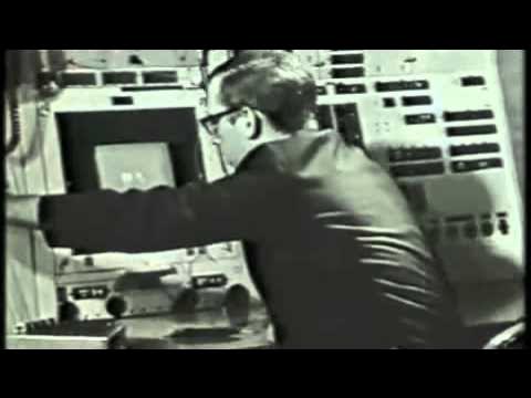
Ivan Sutherland Sketchpad Demo 1963 — Interface Studies

Interface Studies

Ivan Sutherland's system replaces punched cards with real-time graphical constraints and light-pen input to transform computers from passive calculators into interactive design partners.

AI-assisted summary of Ivan Sutherland Sketchpad Demo 1963 — original source. Check the original for full context.

Source published:

Key ideas

  • Ivan Sutherland's Sketchpad introduces a graphical man-machine communication language on MIT's TX-2 computer, replacing punch-card ritual programming with an interactive design assistant. (0:05)
  • The light pen interface integrates a 'gravity field' mechanism that snaps imprecise freehand drawing to lines and vertices, enabling sloppy human input to yield exact geometric drawings. (4:00)
  • Sketchpad maintains a 2-mile virtual canvas within a 7-inch oscilloscope display and supports master-instance hierarchies where editing a master component propagates changes to all instances. (8:24)
  • Extensions to the system demonstrate 3D wireframe editing in four-view quadrants, real-time hidden-line elimination by Dr. Lawrence Roberts, and direct visual compilation of graphical flowcharts into executable software. (12:04)

Detailed notes

## Background Published on YouTube by the channel Interface Studies on May 30, 2012, this video presents a 1960s television broadcast documenting Ivan Sutherland's seminal 1963 MIT doctoral thesis project, Sketchpad. The program explores how Sketchpad—running on the room-sized TX-2 computer at MIT's Lincoln Laboratory—pioneered interactive graphical user interfaces, computer-aided design, and human-computer communication.

## TL;DR Hosted by MIT science reporter John Fitch, the broadcast showcases Sketchpad, a revolutionary system that transforms computers from batch-processing calculating machines into interactive visual design assistants. Researchers demonstrate using a light pen and cathode-ray tube to sketch rough geometric shapes that instantly snap into mathematically precise alignments through constraint satisfaction, alongside reusable master-instance workflows across an expansive virtual canvas. The program further highlights cutting-edge expansions, including Tim Johnson's multi-view 3D wireframe system Sketchpad III, Dr. Lawrence Roberts's real-time solid object modeling with hidden-line elimination, and direct-to-execution graphical flowchart compilation.

## Atmosphere & style The presentation carries the poised, earnest optimism characteristic of early 1960s educational television, framed by John Fitch's thoughtful curiosity and the researchers' quiet technical confidence. Watching the glowing green vectors trace across oscilloscope screens to the tactile accompaniment of clicking toggle switches and push buttons evokes an intimate sense of technological discovery. The dynamic between host and demonstrators feels methodical yet visionary, capturing the exact moment computing shifted from abstract punch cards to direct, visual human-machine interaction.

## Bulletin - [00:05](https://www.youtube.com/watch?v=6orsmFndx_o&t=5s) Ivan Sutherland's Sketchpad introduces a graphical man-machine communication language on MIT's TX-2 computer, replacing punch-card ritual programming with an interactive design assistant. - [04:00](https://www.youtube.com/watch?v=6orsmFndx_o&t=240s) The light pen interface integrates a 'gravity field' mechanism that snaps imprecise freehand drawing to lines and vertices, enabling sloppy human input to yield exact geometric drawings. - [08:24](https://www.youtube.com/watch?v=6orsmFndx_o&t=504s) Sketchpad maintains a 2-mile virtual canvas within a 7-inch oscilloscope display and supports master-instance hierarchies where editing a master component propagates changes to all instances. - [12:04](https://www.youtube.com/watch?v=6orsmFndx_o&t=724s) Extensions to the system demonstrate 3D wireframe editing in four-view quadrants, real-time hidden-line elimination by Dr. Lawrence Roberts, and direct visual compilation of graphical flowcharts into executable software.

## Key takeaways - [00:05](https://www.youtube.com/watch?v=6orsmFndx_o&t=5s) Sketchpad transforms computers from literal, pre-programmed calculating devices into interactive assistants capable of cooperative problem-solving alongside a human designer. - [04:00](https://www.youtube.com/watch?v=6orsmFndx_o&t=240s) The TX-2 computer interface combines an oscilloscope display, toggle switches, push buttons, and a light pen that draws straight lines using a rubber-band technique. - [04:00](https://www.youtube.com/watch?v=6orsmFndx_o&t=240s) A gravity field effect snaps the tracking crosshair directly onto existing endpoints and lines, compensating for human imprecision and enabling high-precision drafting. - [06:04](https://www.youtube.com/watch?v=6orsmFndx_o&t=364s) Sketchpad stores geometric topology rather than static pixels; moving a vertex dynamically recalculates and redraws all attached lines in real time. - [06:04](https://www.youtube.com/watch?v=6orsmFndx_o&t=364s) The digital compass tool draws circles based solely on angular sweep, ignoring radial hand jitter and automatically satisfying geometric constraints upon command. - [08:24](https://www.youtube.com/watch?v=6orsmFndx_o&t=504s) Master drawings can be instantiated into multiple individually scaled and rotated copies; editing a master automatically updates all linked instances across a design. - [08:24](https://www.youtube.com/watch?v=6orsmFndx_o&t=504s) The 7-inch CRT display functions as a movable window over an immense virtual coordinate space measuring approximately two miles on a side. - [12:04](https://www.youtube.com/watch?v=6orsmFndx_o&t=724s) Sketchpad III extends the program into three dimensions, displaying simultaneous front, top, and side orthographic views alongside an independently rotatable perspective view. - [13:32](https://www.youtube.com/watch?v=6orsmFndx_o&t=812s) Direct 3D construction permits latching onto wireframe vertices with the light pen to pull new structures out into space, updating all display projections synchronously. - [14:42](https://www.youtube.com/watch?v=6orsmFndx_o&t=882s) Dr. Lawrence Roberts demonstrates solid-body modeling with real-time hidden-line removal, calculating intersections and occlusions as 3D blocks and wedges penetrate each other. - [16:41](https://www.youtube.com/watch?v=6orsmFndx_o&t=1001s) An interactive flowcharting application allows programmers to draw logic structures and text on-screen, compiling diagrams directly into executable machine code without punched cards. - [17:34](https://www.youtube.com/watch?v=6orsmFndx_o&t=1054s) Designers can begin with rough, nebulous sketches and subsequently impose geometric constraints that are solved simultaneously through relaxation algorithms when a console toggle is flipped.

## Detailed walkthrough ### [00:05](https://www.youtube.com/watch?v=6orsmFndx_o&t=5s) A Graphical Language for Man-Machine Cooperation

John Fitch, an MIT science reporter, introduces the broadcast from MIT's Lincoln Laboratory in Lexington, Massachusetts. He notes that while the laboratory is perhaps best known for its post-World War II contributions to radar and advanced early warning systems, it has also been a crucible for the computer era. To explore how researchers are improving the relationship between humans and computers, Fitch speaks with Professor Steven Coons, an associate professor of mechanical engineering at MIT and co-director of the Computer-Aided Design Project. Coons promises to show Fitch something revolutionary: a human communicating with a computer not through voice, but graphically by drawing. This graphical language is called Sketchpad, a system pioneered by Ivan Sutherland during his doctoral work at MIT.

Coons explains that Sketchpad allows a designer to solve problems step-by-step in full cooperation with the machine, even if the designer does not know the exact problem or its solution at the outset. This represents a massive departure from conventional computing. Historically, using a computer required a complete, highly detailed understanding of the problem and every single step needed to solve it beforehand. The computer acted merely as a literal-minded calculating machine. To program it, users had to write out every detail of the "ritual" on typewriters or punch cards. Sketchpad, by contrast, makes the computer behave like an intelligent human assistant.

"John, we're going to show you a man actually talking to a computer in a way far different than it's ever been possible to do before," says Professor Steven Coons.

- **Location:** MIT's Lincoln Laboratory, Lexington, Massachusetts. - **Key Figures:** Ivan Sutherland (creator of Sketchpad), Professor Steven Coons (co-director of the CAD project), John Fitch (MIT science reporter). - **Core Concept:** Shifting the computer from a literal-minded calculating machine to an interactive, intelligent design assistant.

---

[04:00](https://www.youtube.com/watch?v=6orsmFndx_o&t=240s) The TX-2 and the Light Pen Interface

The demonstration moves to the TX-2 computer, a massive machine built from discrete transistors that serves as the host for Sketchpad. The user interface consists of an oscilloscope display (similar to a television screen but driven directly by the computer), toggle switches, push buttons, and a specialized input device called a light pen. The demonstrator explains how the light pen allows the user to draw directly on the screen. To draw a straight line, the user positions a bright crosshair on the screen, presses a button to command the computer to draw, and then drags the pen. The line stretches out from the initial point to the pen's current position, behaving exactly like a rubber band stretched between two pins.

A key feature of this interface is its tolerance for human imprecision. If the user moves the pen too quickly, the computer loses tracking and stops drawing, which serves as an automatic safety. More importantly, the system employs a "gravity field" effect. When the light pen gets close to an existing line or endpoint, a bright dot in the center of the crosshair automatically jumps onto that line or endpoint. This high-gravity field at endpoints allows the user to make highly precise connections without needing perfect hand-eye coordination.

"This allows me to move my pen quite coarsely, be sloppy while I'm drawing, and get a precision drawing out at the same time," the demonstrator explains.

---

[06:04](https://www.youtube.com/watch?v=6orsmFndx_o&t=364s) Geometric Topology and Constraint Satisfaction

Unlike a traditional paper drawing, which is merely a static collection of lines, Sketchpad understands the underlying geometry and topology of what is being drawn. The demonstrator proves this by pointing the light pen at a vertex where three lines meet. By pressing a button and moving the pen, the user can drag the vertex around the screen; the computer dynamically recalculates and redraws all three attached lines in real time, maintaining their connectivity. The slight delay in rendering is simply the computer performing the necessary calculations to update the geometry.

The demonstrator also showcases how circles are drawn. The user first defines a center point, moves the pen outward to establish an initial radius, and then sweeps the pen to draw the circle. The computer acts as a digital compass, ignoring any sloppy radial deviations of the hand and tracking only the angular position of the pen. If the user sweeps backward, the line is erased. To demonstrate "constraints," the demonstrator draws a circle near a line, leaving a tiny gap. By invoking a constraint command via a toggle switch, the computer runs a program that automatically adjusts the drawing so that the circle perfectly terminates at the line, satisfying the geometric constraint.

"I mean that if I point at this particular point and tell the computer to move that point by another push button command, it will move not only that point but all three lines that are attached to it," the demonstrator points out.

```mermaid flowchart TD accTitle: Sketchpad Interaction and Constraint Loop accDescr: A flowchart showing how a user interacts with Sketchpad using a light pen and buttons, and how the computer calculates and satisfies geometric constraints. User["User with Light Pen"] -->|"Draws/Positions"| Input["Oscilloscope Display & Buttons"] Input -->|"Coordinates & Commands"| TX2["TX-2 Computer"] TX2 -->|"Applies Gravity Field"| Precision["Precision Alignment"] TX2 -->|"Evaluates Constraints"| ConstraintSolver["Constraint Solver"] Precision -->|"Updates Geometry"| Memory["Computer Memory (Topology)"] ConstraintSolver -->|"Adjusts Elements"| Memory Memory -->|"Redraws Vector Graphics"| Input ```

---

[08:24](https://www.youtube.com/watch?v=6orsmFndx_o&t=504s) Master Drawings, Instances, and the Infinite Canvas

The system's power is further amplified by its ability to treat drawings as "masters" and generate "copies" (or instances) of them. The demonstrator saves a drawing and opens a blank virtual sheet of paper. He then calls up multiple copies of the master drawing, demonstrating that each copy can be individually scaled, rotated, and positioned on the screen. This feature is incredibly useful for highly repetitive engineering tasks, such as drawing circuit diagrams filled with resistors and transistors, or structural layouts like bridge bays. If a designer makes a mistake or needs to update a component, they only have to modify the master drawing (for example, erasing a circular arc); Sketchpad automatically propagates that change to every single instance of the component across the entire working drawing.

Fitch asks about the physical scale of this virtual drawing board. The demonstrator explains that while the physical oscilloscope screen is only about 7 inches on a side, it acts merely as a movable window over an immense virtual canvas. The computer's memory maintains a coordinate space representing a sheet of paper that is approximately 2 miles on a side. The demonstrator proves this by scaling a drawing down to its absolute minimum size until it is a tiny dot, and then zooming in so deeply that a single sub-component fills the entire screen, creating a mind-bending "picture within a picture within a picture" effect.

"We can imagine the computer has a fixed sheet of paper behind this window; it scales approximately two miles on a side," the demonstrator explains.

- **Screen Size:** Approximately 7 inches on a side. - **Virtual Canvas Size:** Approximately 2 miles on a side. - **Key Feature:** Master-to-instance propagation (updating a master automatically updates all copies).

---

[11:31](https://www.youtube.com/watch?v=6orsmFndx_o&t=691s) Moving into Three Dimensions

Fitch points out that most objects in the real world are three-dimensional rather than flat, two-dimensional drawings. He asks if Sketchpad can handle 3D design problems. The demonstrator reveals that they have indeed expanded Ivan Sutherland's original program into three dimensions, loading a new software package called Sketchpad III from a magnetic tape drive.

The screen updates to show a single three-dimensional object displayed simultaneously from four distinct viewpoints. The interface is divided into quadrants representing a top view (marked with a "T"), a front view, a side view, and a three-dimensional oblique or perspective view. This multi-view setup mimics traditional engineering drafting standards while allowing real-time, interactive 3D manipulation.

"Yes, we've expanded Ivan's program into three dimensions," the demonstrator says.

[12:04](https://www.youtube.com/watch?v=6orsmFndx_o&t=724s) Sketchpad III: Four-View Projections and 3D Wireframe Manipulation

Tim Johnson demonstrates Sketchpad III on the display, presenting a four-quadrant screen layout configured like standard mechanical engineering drawings alongside an interactive perspective projection. The top-left, bottom-left, and bottom-right displays depict orthographic projections—front, top, and side views—while the fourth window offers an independent perspective view of the three-dimensional space. By turning controls, the operator can rotate the perspective projection independently around an axis perpendicular to an imaginary floor, leaving the three orthographic projections fixed. The object currently on display is a wireframe model without solid surface skins, meaning that internal lines and edges on the far side remain fully visible throughout the rotation. When text characters such as an "S" or an "F" positioned on the object's faces spin around toward the back, they appear reversed to the viewer.

```mermaid flowchart TD accTitle: Sketchpad III Four-View Architecture accDescr: Diagram illustrating the four quadrants of the Sketchpad III display with three linked orthographic views and one independently rotatable perspective view. subgraph QuadViews["Screen Display (Sketchpad III)"] TopLeft["Front View (Orthographic)"] BottomLeft["Top View (Orthographic)"] BottomRight["Side View (Orthographic)"] Perspective["Perspective View (Independently Rotatable)"] end Input["Light Pen Input"] --> QuadViews ```

Drawing in three dimensions mirrors the two-dimensional workflow by using a light pen to manipulate a tracking point across the projections. When the light pen latches onto an "S" located on one surface, moving it causes four tracking dots to move simultaneously across all four display quadrants. In the side view, the dot tracks the letter directly, while in the other views the plane is seen edge-on, restricting the dot's motion to a back-and-forth path across a single line. The interviewer questions whether the system can construct original 3D geometry rather than just tracking existing paths, asking: “Can you actually draw something in all three dimensions simultaneously?”

- The display layout mirrors traditional mechanical drafting conventions, coupling three orthographic projections with an independently rotatable perspective window. - The wireframe display lacks opaque surface clipping, causing rear geometry and text like the letter "F" to appear backwards when facing away from the camera. - Latching the light pen onto an element projects a single geometric coordinate across all views at the same time, maintaining geometric consistency.

---

[13:32](https://www.youtube.com/watch?v=6orsmFndx_o&t=812s) Direct 3D Construction, Distortion, and Surface Modeling

To demonstrate direct construction, Johnson builds a three-dimensional roof on top of the existing wireframe structure. He latches the light pen onto a corner of the building's top plate and pulls the lines up into a peak to form a pyramid-like roof. Checking the orthographic projections, the interviewer observes, “I can see from the side view it's a false front house,” noticing that the newly drawn element has established a distinct profile across views. Johnson then shows that the flexible editing capabilities of 2D Sketchpad carry over into 3D: by latching onto an edge line of the structure, he drags it outward into space, warping the geometry. Rotating the perspective view reveals an irregularly stretched, distorted house model.

When the interviewer asks whether Sketchpad can expand beyond simple straight lines into curved surfaces—such as those needed to design an automobile body—Johnson answers affirmatively, stating, “We're well on our way with surfaces, we've begun the programming there and we understand them we think pretty well.”

- Latching to existing vertices allows users to pull out three-dimensional shapes directly on screen, such as a roof pyramid over a house frame. - Any line or vertex can be gripped with the light pen and pulled off-axis to distort the 3D model, updating all four viewports in real time. - Ongoing development includes curved surface mathematics, aiming toward practical applications in industrial styling like automotive body design.

---

[14:42](https://www.youtube.com/watch?v=6orsmFndx_o&t=882s) Dr. Lawrence Roberts on Solid Objects and Hidden-Surface Elimination

The focus shifts to Dr. Lawrence Roberts of MIT Lincoln Laboratory, who addresses the fundamental limitations of pure wireframe graphics. Roberts explains that manipulating genuine solid bodies inside a computer requires modeling surfaces so that objects occlude what lies behind them. He demonstrates a 3D model of a block resembling a piece of wood on the TX-2 display. Unlike Johnson's wireframe house, Roberts's software performs hidden-line removal: as he rotates the block in real time, edges positioned behind front faces automatically disappear. When the interviewer marvels that occluded lines vanish completely, Roberts confirms, “That's right, and so this is just one of my models that I can work with.”

Roberts calls up additional primitives, loading a 3D wedge, scaling it down, and rotating it in space. He drives the wedge directly into and through the block. The computer recalculates the intersections dynamically, hiding portions of the wedge that slip inside or behind the block while rendering the visible segments where the shapes intersect. The interviewer observes that this spatial realism transforms the display into a convincing window looking into a three-dimensional world with distinct foreground and background depths.

```mermaid flowchart LR accTitle: Real-Time Solid Object Hidden-Surface Workflow accDescr: Flow diagram showing how 3D primitives are modeled, intersected, and rendered with real-time hidden-line removal. subgraph Modeling["3D Solid Operations"] Block["Solid Block Model"] Wedge["3D Wedge Primitive"] Transform["Scale / Rotate / Translate"] end subgraph Computation["Computer Processing"] Intersect["Intersection Calculation"] Occlusion["Hidden-Line Elimination"] end subgraph Output["Display Scope"] Render["Rendered Solid Appearance"] end Block --> Transform Wedge --> Transform Transform --> Intersect Intersect --> Occlusion Occlusion --> Render ```

- Roberts transitions the system from open wireframes to solid boundary representations where opaque faces occlude back-facing edges. - As solid primitives like blocks and wedges rotate or pass through one another, the software calculates geometric intersections and suppresses hidden vectors on the fly. - The real-time removal of occluded geometry produces an illusion of true spatial depth on a flat cathode-ray tube.

---

[16:41](https://www.youtube.com/watch?v=6orsmFndx_o&t=1001s) Interactive Graphical Flowcharting and Program Compilation

Roberts presents an application of Sketchpad aimed at software engineering: visual computer program design through flowcharts. Ordinarily, a programmer diagrams a flowchart by hand on paper, detailing logical processes, comparisons, and conditional branches, before manually transcribing those instructions into punched cards or code. Roberts shows an active flowchart drawn directly on the cathode-ray tube using Sketchpad, populated with boxes connected by branching directional flow paths.

Each box contains textual statements directing the computer to carry out a specific task, compare values, or perform conditional branching tests. Roberts highlights the direct bridge this builds between visual thinking and software execution: “Here we go directly from him drawing the flowchart and stating what each piece is, putting the statements inside the boxes, to a compiled program which he may execute.” The system bypasses physical punched-card entry, compiling the user's diagram into executable instructions straight from the display.

- Interactive flowcharting lets programmers create calculation blocks, comparison checks, and branch decisions directly on screen. - The interface replaces manual code transcription and punched card decks by compiling the drawn diagram directly into executable machine code. - Textual instructions are inserted directly within the graphical boundaries of the flowchart boxes.

---

[17:34](https://www.youtube.com/watch?v=6orsmFndx_o&t=1054s) Conceptual Drafting, Constraint Satisfaction, and Master Instances

The presentation returns to the core philosophy of Sketchpad's constraint-driven design. The designer notes that at the start of any creative process, ideas are vague: “When I'm beginning a design I have a very nebulous idea what I want to have in mind.” Sketching rough geometry directly on the display helps clarify thinking. Rather than requiring the draftsman to input exact dimensions from the outset, Sketchpad lets the user draw crude lines and refine them later as physical design criteria and stress constraints become clear.

```mermaid flowchart TD accTitle: Constraint Satisfaction Workflow accDescr: Sequence showing how rough sketches become exact geometry through applied constraints and toggle execution. Rough["1. Rough Sketch Drawn with Light Pen"] --> Constraints["2. Assign Constraints (Horizontal, Vertical, Point Alignment)"] Constraints --> Toggle["3. Flick Control Toggle (Satisfy Constraints)"] Toggle --> Relaxation["4. System Relaxes Rubber-Band Network"] Relaxation --> Exact["5. Clean, Exact Geometric Shape"] ```

To illustrate, the designer draws an irregular four-sided shape, then applies horizontal constraints to two opposite lines and vertical constraints to the other two by pointing at them with the light pen and pressing a push-button. The lines stay crooked because the constraints are not applied immediately; the software waits for an explicit command. The demonstrator explains, “Well now nothing has happened yet, because remember I still must tickle that toggle over there to command the computer to satisfy these constraints.” The interviewer observes: “See, it won't actually let those rubber bands relax then until you say so.” Flipping the toggle relaxes the rubber-band model, snapping the crooked polygon into a crisp rectangle. The demonstrator contrasts this with standard mechanical tools:

> “In other words, you don't have to draw exactly at the beginning like you have to do in drafting.”

He concludes by preparing to demonstrate another capability of Sketchpad: pulling up instanced copies of earlier "master pictures" to assemble complex, reusable hierarchies.

- The constraint solver allows designers to sketch loose visual topologies first and enforce rigorous geometric relationships later. - Constraints such as horizontal and vertical alignments are assigned with the light pen and push-buttons, then solved simultaneously upon flipping a physical console toggle. - The relaxation algorithm treats drawn paths like an interconnected network of rubber bands, snapping them to exact mathematical constraints upon execution. - Master drawings can be stored and recalled as sub-pictures, forming the foundation of modular, hierarchical computer-aided design.

## Notable quotes > [17:34](https://www.youtube.com/watch?v=6orsmFndx_o&t=1054s) You don't have to draw exactly at the beginning like you have to do in drafting. — The demonstrator

## Mentioned Ivan Sutherland, Sketchpad, Sketchpad III, TX-2, John Fitch, Professor Steven Coons, Tim Johnson, Dr. Lawrence Roberts, MIT Lincoln Laboratory, Computer-Aided Design Project, Massachusetts Institute of Technology

## Video description Watch now: History of The Graphical User Interface (GUI): A Wonderful Curse https://youtu.be/fHMPGhezj0s?si=DuBg3tOL_hiEG7sY

This video is a TV show made about the software Ivan Sutherland developed in his 1963 thesis at MIT's Lincoln Labs, "Sketchpad, A Man-Machine Graphical Communication System", described as one of the most influential computer programs ever written. This work was seminal in Human-Computer Interaction, Graphics and Graphical User Interfaces (GUIs), Computer Aided Design (CAD), and contraint/object-oriented programming. While watching this video, remember that the TX-2 computer (built circa 1958) on which the software ran was built from discrete transistors (not integrated circuits -it was room-sized) and contained just 64K of 36-bit words (~272k bytes).

http://mskayyali.com

[Source](https://www.youtube.com/watch?v=6orsmFndx_o)

中文简报

麻省理工学院应用Sketchpad将TX-2打造为交互式设计引擎 伊万·萨瑟兰的系统通过实时图形约束与光笔输入取代打孔卡,将计算机从被动计算器转变为交互式设计伙伴。 在麻省理工学院科学记者约翰·菲奇主持的节目中,展示了开创性的Sketchpad系统,该系统将计算机从批处理计算机器转变为交互式视觉设计助手。研究人员演示了如何利用光笔和阴极射线管绘制粗略的几何形状,并通过约束满足使其瞬间吸附为数学上精确的对齐形态,同时在广阔的虚拟画布上展示了可复用的母版-实例工作流。节目还重点介绍了前沿拓展成果,包括蒂姆·约翰逊的多视图三维线框系统Sketchpad III、劳伦斯·罗伯茨博士消除隐藏线的实时实体对象建模,以及将图形流程图直接编译为可执行程序的技术。 伊万·萨瑟兰的Sketchpad在麻省理工学院的TX-2计算机上引入了图形化的人机通信语言,以交互式设计助手取代了打孔卡程序编制。 (0:05) 光笔界面整合了“重力场”机制,可将不精确的徒手绘制吸附到线条和顶点上,使粗糙的人工输入能够生成精确的几何图形。 (4:00) Sketchpad在7英寸的示波器显示器内维持着一个2英里的虚拟画布,并支持母版-实例层级结构,编辑母版组件即可将改动同步至所有实例。 (8:24) 该系统的扩展展示了四象限多视图中的三维线框编辑、劳伦斯·罗伯茨博士实现的实时隐藏线消除,以及将图形流程图直接可视化编译为可执行软件。 (12:04)

Reading summary

Demonstrated at MIT's Lincoln Laboratory in 1963, Ivan Sutherland's Sketchpad redefined human-computer interaction by shifting computers from rigid, batch-programmed calculating machines into interactive visual partners capable of understanding geometric topology, spatial constraints, and multi-dimensional models in real time. Light Pen Interface and Precision Aids (4:00) Hosted on the transistorized TX-2 computer, Sketchpad replaced punch cards and paper drafting with direct graphical interaction on an oscilloscope screen. Using a light pen alongside push buttons and toggle switches, the user positions a crosshair and draws vector lines that stretch like rubber bands between points. To bridge the gap between human manual imprecision and machine exactness, the system incorporates two automated aids: tracking halts if the pen moves too fast, and a high-gravity field automatically snaps the crosshair onto existing lines and endpoints. This allows an operator to sketch coarsely while maintaining exact geometric connections. Geometric Topology and Constraint Relaxation (6:04) Unlike static paper drafting, Sketchpad records the geometric relationships and connectivity of drawn elements. Pointing at a vertex where multiple lines meet and dragging it across the screen causes the computer to recalculate and redraw all attached lines dynamically. Similarly, a digital compass routine ignores radial hand jitter to construct true circles, tracking only the pen's angular sweep. The system separates initial drafting from dimensional precision through constraint satisfaction. A designer can draw irregular, crooked polygons without predefined measurements, assign geometric rules such as horizontal and vertical alignments via buttons, and then flip a console toggle. This command runs a relaxation algorithm that treats lines like an interconnected elastic network, automatically resolving and snapping the rough sketch into an exact geometric shape. Master Copies and the Infinite Canvas (8:24) Sketchpad introduced modular, hierarchical computer-aided design by treating drawings as reusable master templates. An operator can define a master component—such as an electronic component or a structural truss—and instantiate multiple copies across a project. Each instance can be rotated, scaled, and placed independently, while any retroactive modification to the master template automatically propagates to all instances. This drawing workspace is not restricted by the physical seven-inch oscilloscope screen. The display acts as an adjustable viewport over an internal coordinate memory representing a virtual canvas roughly two miles on a side, permitting extreme zoom ranges from sprawling architectural overviews down to microscopic details. Three-Dimensional Modeling and Visual Programming (11:31) Expanding beyond flat 2D drafting, Tim Johnson demonstrated Sketchpad III, which organizes the screen into three linked orthographic engineering views (front, top, side) alongside an independently rotatable perspective projection. Operating the light pen in any quadrant simultaneously tracks across all four viewports, allowing users to draw roofs onto house frames or distort wireframe volumes off-axis in real time. To resolve the visual confusion of wireframe models where rear edges remain visible, Dr. Lawrence Roberts implemented solid boundary modeling with dynamic hidden-line removal. As solid blocks and wedges rotate or penetrate each other, the TX-2 recalculates intersections and eliminates occluded lines. Roberts also demonstrated Sketchpad's utility for software engineering by drawing interactive flowcharts with logic statements directly on screen, which the system compiled into executable machine instructions without manual punched-card transcription. While Sketchpad successfully established real-time constraint solvers, instancing, and solid rendering on the TX-2, complex practical capabilities such as mathematical surface modeling for curved industrial designs (like automobile bodies) remained ongoing development goals at the time of the 1963 demonstration.

精炼阅读摘要

1963年麻省理工学院林肯实验室展示的Sketchpad系统,由Ivan Sutherland在其博士研究期间开创,标志着计算机从死板的打孔数值计算工具转变为能够理解几何拓扑并与人类协同创作的智能图形设计助手。 图形交互范式与物理容错输入 (4:00) 在麻省理工学院林肯实验室的TX-2晶体管计算机上,演示者展示了脱离传统纸带和打孔卡的交互形式。用户通过示波器阴极射线管屏幕、控制按钮、拨动开关以及光笔进行直接操作。绘制直线时,用户在屏幕上定位光标并拖拽光笔,线条像在图钉间拉伸的“橡皮筋”一样动态延展。麻省理工学院机械工程副教授Steven Coons指出,该系统彻底颠覆了必须预先确定所有解题步骤的传统编程模式。 该输入界面具备专门针对人类操作不精准性的容错机制。若光笔移动过快超出系统追踪范围,计算机会自动终止绘制以确保安全;更关键的是系统引入了“重力场”机制。当光笔靠近已存在的线条或端点时,光标中心的亮点会自动吸附过去。这一设计使用户即使手部动作粗糙或缺乏精细协调能力,依然能绘制出高精度的连接点与线段。 几何拓扑关联与约束松弛求解 (6:04) 与仅记录静态线条的传统图纸不同,Sketchpad具备理解底层几何结构与拓扑关联的能力。当演示者使用光笔指向三条线交汇的顶点并下达移动指令时,拖动该顶点会导致计算机实时重新计算并重绘与之相连的所有三条线,始终保持网络连接性。在绘制圆弧时,系统充当数字圆规,忽略手部径向抖动并仅追踪角位移,反向划动即可擦除。 系统的另一核心是几何约束求解机制。设计初期往往概念模糊,用户可先绘制粗糙的不规则四边形,再通过光笔和按钮为其指定对边平行、垂直或端点重合等几何约束。由于系统不会自动执行约束,绘制线条起初保持弯曲;只有当操作者拨动控制台上的实体开关时,松弛算法才会将整套“橡皮筋网络”拉紧,瞬间将歪斜的多边形规整为严格精确的长方形。 广域虚拟画布与主图层级复用 (8:24) 演示表明,物理尺寸边长仅约7英寸的示波器屏幕,本质上只是一个可移动的视口,其背后对应着计算机内存中边长约2英里的巨型虚拟绘图空间。演示者通过缩放操作证实了这一点:图纸既可以缩小为一个极小的微缩点,也可以极度放大直至单一子构件填满整个显示器,呈现出层层嵌套的深层视野。 在此空间基础上,Sketchpad支持将绘制内容保存为“主图”(Master),并调出任意数量的复制副本(Instance)。每个副本都可以独立进行位置平移、角度旋转与尺寸缩放,极大地便利了电路图或桥梁结构等重复性工程设计。若设计方案发生变更,设计人员只需在主图中修改某一局部(例如擦除一条圆弧),系统便会自动将修改同步传播至全图所有调用的实例构件中。 三维多重视图与实体表面消隐 (11:31) 针对真实世界三维设计需求,Tim Johnson展示了扩展后的Sketchpad III系统。屏幕被划分为四个象限,分别显示顶视、前视、侧视三个正交工程投影视图,以及一个可独立绕垂直轴旋转的三维透视窗口。操作者使用光笔拉动三维线框结构上的顶点时,四个视口会同步更新坐标,甚至可直接在平房框架上拉出金字塔形的立体屋顶。Johnson表示,开发团队已开始推进曲面数学模型的编程工作,旨在支持未来汽车车身等工业造型设计。 针对线框模型缺乏不透明表面、导致背面线条与字符翻转透视的局限,林肯实验室的Lawrence Roberts博士展示了三维实体建模与实时消隐算法。当在TX-2上旋转实心木块或将三维楔形体穿入实体块内部时,软件动态计算空间交集并实时剔除被遮挡的隐藏线条与背面轮廓,使平面的阴极射线管展现出具有明确前后遮挡关系的真实深度效果。 视觉化流程图与程序直接编译 (16:41) 除了机械与结构工程制图,Roberts博士进一步展示了Sketchpad在软件工程中的实际应用。传统编程需要开发人员先在纸上手绘逻辑流程图,再人工将分支与判断逻辑转写为穿孔卡片。Sketchpad允许工程师直接在屏幕上绘制流程图框,并用带箭头的方向流线连接各个逻辑节点。 每个图形框内部均可直接填入具体的运算语句、变量数值比较或条件分支指令。系统能够直接解析屏幕上绘制的图形拓扑结构与框内文本,当场将其编译为可执行的机器程序。该应用打破了图形构思与底层代码执行之间的介质隔阂,使用户无需接触物理打孔卡即可完成程序设计与调试。 1963年的Sketchpad与Sketchpad III演示验证了参数化约束、实例继承、多视图联动与实时消隐等现代计算机辅助设计(CAD)的基础构想。尽管受限于早期硬件性能与初步的曲面算法,该系统确立了计算机作为交互式视觉思考媒介的技术路径。

Detailed notes — zh

## Background 该视频由 YouTube 频道 Interface Studies 于 2012 年 5 月 30 日发布。视频内容是一档关于 Ivan Sutherland 于 1963 年在麻省理工学院林肯实验室(MIT Lincoln Laboratory)完成的博士论文成果——Sketchpad 系统的电视专题节目,展示了这一运行在仅有约 272KB 内存的 TX-2 计算机上、被誉为计算机图形学与人机交互开山之作的图形化交互软件。 ## TL;DR 节目深入演示了 Sketchpad 如何打破传统穿孔卡片批处理计算模式,开创以光笔和 CRT 示波器为媒介的实时图形交互新范式。演示者展示了橡皮筋绘图、重力场节点吸附、拓扑几何约束求解以及母版与副本(Master/Instance)联动复用等核心机制,支持在 2 英里见方的虚拟画布上自由缩放。随后,节目进一步展示了具备正交与透视四视图的三维线框建模系统 Sketchpad III、劳伦斯·罗伯茨博士研发的实时隐藏线消除实体建模技术,以及直接用光笔绘制并编译执行的可视化流程图编程系统。 ## Atmosphere & style 全片洋溢着 1960 年代科技探索黄金期的严谨与开拓气息,黑白电视特有的胶片质感与控制台密集的物理拨动开关相互交织,烘托出强烈的复古未来主义氛围。主持人 John Fitch 与 Steven Coons 等科学家之间的对话求真务实且充满启发性,既有对全新人机协作哲学的理论思辨,又有面对光笔吸附、图形瞬间自动“立正”时的真诚赞叹。观看本片仿佛亲历计算文明黎明时期的历史现场,屏幕前后的人类与机器首次以图形达成默契对话,节奏沉稳而极具远见震撼力。 ## Bulletin - [00:05](https://www.youtube.com/watch?v=6orsmFndx_o&t=5s) Ivan Sutherland 在 MIT 林肯实验室开发的 Sketchpad 首次确立了人机图形交互范式,摆脱了传统穿孔卡片的死板计算,让计算机扮演具备实时几何理解能力的人类助手。 - [08:31](https://www.youtube.com/watch?v=6orsmFndx_o&t=511s) Sketchpad 在 7 英寸的 CRT 示波器上提供了单边长达约 2 英里的连续虚拟图纸空间,并开创了面向对象设计核心的母版与副本(Master / Instance)联动机制。 - [14:41](https://www.youtube.com/watch?v=6orsmFndx_o&t=881s) 林肯实验室将系统拓展至三维建模(Sketchpad III),劳伦斯·罗伯茨博士展示了实时的隐藏线消除(Hidden-line removal)与实体空间求交计算技术。 - [17:33](https://www.youtube.com/watch?v=6orsmFndx_o&t=1053s) Sketchpad 首创几何约束求解引擎,允许工程师先随意勾勒粗略草图,随后通过算法强制满足几何约束以自动精确对齐图形。 ## Key takeaways - [00:05](https://www.youtube.com/watch?v=6orsmFndx_o&t=5s) Sketchpad 奠定了现代人机交互(HCI)与计算机辅助设计(CAD)的基石,使人机沟通从枯燥的打字代码转向直观的图形化语言。 - [00:05](https://www.youtube.com/watch?v=6orsmFndx_o&t=5s) 传统计算机仅被作为机械式批处理工具,而 Sketchpad 使机器能够理解图纸背后的拓扑关系与动态变化,展现出“外在智能”。 - [04:00](https://www.youtube.com/watch?v=6orsmFndx_o&t=240s) 林肯实验室的 TX-2 计算机配合阴极射线示波器(CRT)和光笔,构成了世界上首个支持实时动态图形输入的交互工作站。 - [04:00](https://www.youtube.com/watch?v=6orsmFndx_o&t=240s) 系统设计了类似橡皮筋的线条动态牵引机制,并结合数学上的“重力场”吸附算法,容忍操作者的粗糙绘图并确保节点精确闭合。 - [06:04](https://www.youtube.com/watch?v=6orsmFndx_o&t=364s) Sketchpad 具备拓扑理解能力,拖动任意交点均会带动相连线段实时拉伸重算,画圆时也能自动过滤径向抖动仅追踪角位移。 - [08:31](https://www.youtube.com/watch?v=6orsmFndx_o&t=511s) 开创了面向对象中的“母版(Master)与副本(Copy)”机制,修改基础母版图元会自动触发全局所有引用实例的联动更新。 - [08:31](https://www.youtube.com/watch?v=6orsmFndx_o&t=511s) 7 英寸的物理示波器屏幕本质是一扇虚拟视窗,其底层坐标系构建了单边约 2 英里、支持深度无限缩放的虚拟连续图纸空间。 - [12:04](https://www.youtube.com/watch?v=6orsmFndx_o&t=724s) Sketchpad III 实现了三维正交多视图(顶视图、前视图、侧视图)与透视视图的联动交互,能够在三维空间中通过光笔直接拉伸立体线框。 - [14:41](https://www.youtube.com/watch?v=6orsmFndx_o&t=881s) 劳伦斯·罗伯茨博士突破了纯线框模型的局限,引入实体几何表达与实时隐藏线消除算法,展现出前后遮挡的逼真立体感。 - [14:41](https://www.youtube.com/watch?v=6orsmFndx_o&t=881s) 系统实现了早期三维实体的布尔相交解算,能实时计算出不同几何形体在空间中相交的边界截线与遮蔽关系。 - [16:40](https://www.youtube.com/watch?v=6orsmFndx_o&t=1000s) 罗伯茨利用 Sketchpad 展示了可视化流程图编程,光笔绘制的逻辑方块与连线可被系统直接编译为机器可执行代码,跳过了穿孔卡片步骤。 - [17:33](https://www.youtube.com/watch?v=6orsmFndx_o&t=1053s) Sketchpad 契合了人类在设计初期构想模糊的心理特点,允许从不规则草图起步,依靠约束求解器(如水平/垂直约束)一键规范化几何形态。 ## Detailed walkthrough ### [00:05](https://www.youtube.com/watch?v=6orsmFndx_o&t=5s) 图形语言的诞生:人机交互的新范式 在麻省理工学院(MIT)位于马萨诸塞州列克星敦的林肯实验室(Lincoln Laboratory),主持人 John Fitch 开启了本期《MIT Science Reporter》节目。这所知名实验室自二战以来在雷达和预警系统等国防领域发挥了核心作用,同时也是早期计算机时代的摇篮之一。John Fitch 专访了 MIT 机械工程副教授兼计算机辅助设计(Computer Aided Design, CAD)项目联合主任 Steven Coons 教授,探讨林肯实验室在改善人机关系方面的突破性进展。Coons 教授在开场时便抛出一个颠覆传统的概念:他们将展示一个人以一种前所未有的方式“与计算机交谈”。 面对 Fitch “绝不是用声音交谈吧”的疑问,Coons 解释说,这种交流是通过“图形化语言”进行的。操作者在屏幕上绘制图案,而计算机则能完全理解这些图纸。这种图形语言系统被称为 Sketchpad,最初由 Ivan Sutherland 在攻读博士学位期间开发。在这一体系下,设计者可以一步一步地探索并解决问题,即使最开始并不清楚确切的问题是什么,也没有完整的解决方案,但在设计者与计算机之间能够建立起一种深度的“全面协作”。 以往利用计算机解决问题,需要工程师预先将问题研究得极为透彻,明确求解所需的每一个具体步骤,使得计算机本质上沦为一台极度精密的计算机器。以往操作者必须通过打字机或穿孔卡片,机械而繁琐地写下整个求解流程的所有“仪式”,因为计算机思维非常死板。而 Sketchpad 带来了根本性改变,正如 Steven Coons 教授所指出的那样:“如今我们正让计算机变得更像一个人类助手,并且计算机似乎具备了某种智能——它实际上并没有真正的智能,只有我们赋予它的智能,但它看起来却仿佛有了智慧一样。”(“...now we're making the computer be more like a almost like a human assistant and the computer will will seem to have some intelligence it doesn't really only the intelligence that we put in it but it will seem to have intelligence...”) ```mermaid flowchart LR accTitle: 传统计算模式与 Sketchpad 图形交互模式对比 accDescr: 对比了传统的穿孔卡片批处理计算模式和基于光笔与阴极射线管的 Sketchpad 人机协作交互模式 subgraph TRAD ["传统计算模式"] direction TB T1["穿孔卡片 / 纸带"] --> T2["批处理执行预设指令"] T2 --> T3["输出数值结果(纯计算工具)"] end subgraph SKETCH ["Sketchpad 图形交互模式"] direction TB S1["光笔绘制与按钮输入"] --> S2["实时几何拓扑计算"] S2 --> S3["显示器即时反馈与人机协作"] end ``` ### [04:00](https://www.youtube.com/watch?v=6orsmFndx_o&t=240s) TX-2 计算机与 Sketchpad 的基础绘图机制 得益于林肯实验室的 TX-2 计算机配备了大量按钮、拨动开关(Toggle switches)以及配套外设,它在 1961 年成为了开发 Sketchpad 系统的绝佳平台,让机器能够成为图形领域的连贯协作者。演示人员向 Fitch 介绍了具体的硬件操作方式:主显示装置是一台由计算机驱动的阴极射线示波器(CRT 示波管),相当于一台由计算机控制的电视屏幕;输入端则是一支光笔(Light Pen)。 利用 Ivan Sutherland 编写的程序,工程师能够直接在示波器屏幕上绘制直线和圆弧,这覆盖了传统绘图板的核心需求。绘图时,屏幕上的十字光标中心会出现一个亮点。演示者将亮点对准预想的起点,按下按钮发送绘图指令,随后光笔无论移动到哪里,线条都会同步生成。这一过程被生动地比喻为橡皮筋效果:“这非常像一条橡皮筋被固定在两个图钉之间,一个钉在屏幕上,另一个在我的光笔上,所以我可以随意将它放置在任何我想放的位置。” 如果光笔移动过快导致丢失追踪(Lost tracking),计算机会自动停止划线。当光笔中心的光斑靠近已有线条或端点时,亮点会自动“吸附”过去。演示人员解释,这在数学上被设计成类似于一个“重力场”(Gravity field),端点处的引力场甚至更强。这种设计让绘图者即使手抖或操作极其粗糙随意(Sloppy),也能由计算机计算出极其精确的工程图。 - **输入输出媒介**:计算机驱动的示波器屏幕(显示端)与光笔、专用控制按钮、拨动开关(输入端)。 - **橡皮筋机制**:起点固定在屏幕上,终点跟随光笔动态牵引。 - **重力场吸附**:线条与几何端点具备重力吸附判定,可容忍粗糙绘图并自动确保节点精确对接。 ### [06:04](https://www.youtube.com/watch?v=6orsmFndx_o&t=364s) 拓扑理解、几何约束与参数求解 演示者随后展示了 Sketchpad 与普通纸笔涂鸦的本质差异:纸笔画出的只是一张静止的死图像,而计算机理解的是图纸背后的拓扑几何关系(Geometry of the drawing)。当演示者绘制了三条汇聚于同一点的直线后,他用光笔指向交点并按下移动按钮,该节点移动的同时,相连的三条直线全部自动拉伸变形并保持连接。Fitch 注意到了指令发出与图形变化之间的微弱停顿,演示者证实这正是因为计算机正在实时计算所有几何位置的动态变化。如果不慎画错,只需用光笔指向对应线条并按下删除按钮,即可瞬间将其抹除。 在绘制圆弧时,演示者先确定圆心,再向外移动到初始半径点,按下另一枚按钮起步。此时调整绘图比例使整圆显现后,光笔无论在径向如何晃动、甚至光笔超出屏幕,计算机都会完全忽略径向偏差,仅拾取角度位移。这意味着计算机会主动扮演规尺的角色——绘制直线时相当于直尺,绘制弧线时相当于圆规。若逆向划动光笔,已画出的圆弧还会被动态擦除。 更有突破性的是 Sketchpad 的“约束”(Constraint)机制。演示中,演示者尝试将圆弧的一端接在一条直线端点上,但由于粗画,两者之间其实存在肉眼可见的微小间隙(Nub)。演示者拉开端点展示它们原本并未真正闭合,随后通过操纵台上的拨动开关调入约束求解程序:“计算机接收到约束指令后,即刻自动将圆弧精确闭合在直线上,强行约束图形按照数学逻辑表现。” - **拓扑连接特性**:移动单一点坐标时,所有依赖于该点的线段均保持连接并实时重算。 - **约束求解器**:不仅依靠绘图动作,还能通过独立算法强制执行几何条件(如线段与圆弧精准闭合)。 - **极坐标绘图逻辑**:绘制圆弧时锁定半径,只对光笔的角位移做动态积分。 ### [08:31](https://www.youtube.com/watch?v=6orsmFndx_o&t=511s) 主从图纸与实例复用:无边界的虚拟图纸空间 在阐述约束系统的进一步应用时,演示者切换到了“第二张图纸”。通过操作台上的拨动开关,系统可以随时存储当前画作并调取任意编号的空白画卷或已有图纸。在此,演示者展示了面向对象架构的雏形——“母版”(Master)与“副本”(Copy / Instance)概念。他将刚才画出的图形设为主图,并在新画布上多次调用其副本;每一个调出的副本都可以被独立地就地操纵:缩小、放大、旋转以及自由放置。 这种模块化复用对于包含大量重复结构的工程设计具有划时代意义,例如绘制电路图或桥梁桁架。Fitch 敏锐地指出:“哦,如果你在画一张电路图,你可以预先画好一些电阻器或晶体管并保存起来,然后随时调用任意多个,对吧?”(“Oh if you were drawing a circuit diagram you might have little resistors or transistors or something already drawn and stored away and you could call up as many of those as you wanted right.”)主从模式的杀手级功能在于联动更新:一旦设计人员在后续工作中发现母版存在缺陷并擦除多余弧线,系统内所有图纸中引用该组件的工作副本都会自动同步更新,彻底免去了在纸面手工排查、逐张修改的繁杂苦工。 随后 Fitch 询问示波器屏幕所代表的图纸实际大小。演示者透露了一个惊人的事实:物理示波器屏幕长宽仅约 7 英寸,但它仅相当于一扇虚拟“视窗”(Window);在视窗背后,计算机内存中所构建的虚拟连续纸张,其单边尺度可达约 2 英里(Approximately 2 miles on a side)。演示者现场演示了这种无限缩放与画中画嵌套结构:将主图不断缩微至视网膜极限的单个亮点,再调入副本进行多重嵌套,只要数据仍在内存中,极度微观的细节在放大后依然分毫不差。 最后,针对 Fitch 提出的“现实世界由三维物体构成而非平面”的问题,演示者证实林肯实验室已将 Ivan Sutherland 的程序拓展至三维几何空间。随着演示者从磁带机(Magnetic Tape)中调入三维程序,示波器屏幕上清晰地同时切分出顶视图(T 标示)、前视图以及侧视图这四个视图,展现了 Sketchpad 正在迈向三维立体建模的新纪元。 ```mermaid flowchart TD accTitle: Sketchpad 母版与实例联动架构 accDescr: 展示修改母版图形时,所有引用的副本实例自动同步几何变更的联动机制 subgraph MASTER ["母版设计 (Master Drawing)"] M1["定义基本构件 (如电阻/晶体管/几何图样)"] M2["母版修改 (删除或调整图元)"] end subgraph INSTANCES ["工作图纸中的实例 (Instances / Copies)"] I1["实例 A (缩小/平移)"] I2["实例 B (旋转角度)"] I3["实例 C (多重嵌套)"] end M1 -->|"生成与引用"| I1 M1 -->|"生成与引用"| I2 M1 -->|"生成与引用"| I3 M2 -.->|"全局联动更新"| I1 M2 -.->|"全局联动更新"| I2 M2 -.->|"全局联动更新"| I3 ``` - **母版-副本关系**:支持组件独立缩放、旋转与多次实例化,修改母版自动全局生效。 - **虚拟画布坐标域**:7 英寸物理屏幕对应内存中约 2 英里见方的虚拟空间,支持深层次多级缩放。 - **三维多视图映射**:从磁带载入三维核心模块,在同一屏幕上联合呈现正交四视图(顶视图、前视图、侧视图等)。 ### [12:04](https://www.youtube.com/watch?v=6orsmFndx_o&t=724s) Sketchpad III 的四视图交互与三维线框建模 演示者展示了三维计算机辅助绘图系统(Sketchpad III)的工作机制。屏幕被划分为四个并列的窗口:其中三个采用传统机械制图的标准正交投影(顶视图、前视图和侧视图),第四个窗口则是透视视图。透视图可以独立于其他三个工程视图进行旋转,绕着垂直于假想地面的旋转轴自由转动。此时屏幕上呈现的是一个没有蒙皮的纯线框模型,因此所有背部线条一览无余;当模型表面带有字母“S”的一侧转到背面时,透视窗口中便清晰地显现出镜像反向的字母。演示者向观众直观地解释这一视觉现象背后的物理本质:“We have a wireframe object here with no fabric covering hence we see the rear lines as they come in behind this s which might be lying in the surface but there is no fabric here so we see everything when the letters go around behind they're backwards.” 通过光笔与屏幕交互,操作者能够在三维空间中直接进行定位与绘制。当光笔锁定侧面上的字母“S”并拖动时,屏幕四个视图中的光标点会同步移动:在侧视图中该点沿着“S”的轮廓走动,而在从侧边缘观察的视图中,它则呈现为单一轴向的往复移动。当主持人询问能否在所有三个维度中真正进行立体建造时,演示者随即演示了如何在现存结构顶部增加一个金字塔形屋顶:光笔精确吸附到底座的四个角点并向上拉伸出锥体,使得侧视图呈现出一个假正面的房屋造型。不仅如此,系统还支持在三维空间中对线段进行任意形变与拉扯,演示者选中棱线向外拖拽后,整栋房屋在重新旋转的透视图中呈现出扭曲的趣味结构。面对主持人关于能否设计汽车等弯曲表面的提问,演示者明确表示曲面建模的程序编制已经展开,团队对三维表面的数学表达与实现已胸有成竹。 - **多视图联动**:包含三个正交投影工程视图(机械制图布局)和一个支持独立绕轴旋转的透视投影视图。 - **三维光笔交互**:光笔在任一视图中拾取点线时,投影点会在所有四个视图中同步计算并联动追踪。 - **拓扑变形与构造**:支持捕捉三维角点搭建复杂体素(如棱锥屋顶),并能直接拖拽局部线条实现非对称扭曲。 --- ### [14:41](https://www.youtube.com/watch?v=6orsmFndx_o&t=881s) 劳伦斯·罗伯茨博士与早期三维实体及消隐技术 镜头转向麻省理工学院林肯实验室(MIT Lincoln Laboratory)的研究人员劳伦斯·罗伯茨博士(Dr. Lawrence Roberts)。罗伯茨指出,蒂姆·约翰逊(Tim Johnson)展示的线框模型虽然构成了三维图形的基础,但若要在计算机中真正模拟和操作实体,就必须摆脱透明骨架的局限,建立对实体表面及其遮挡关系的数学表达。罗伯茨博士在阐释该研究的动机时强调:“However if we want to manipulate solid objects with the computer we want to be able to represent their surfaces and so on as solid.” 罗伯茨在屏幕上调出一个类似木块的几何实体进行动态旋转演示。与纯线框系统截然不同,该程序具备实时的隐藏线消除(Hidden-line removal)能力:当实体转动时,处于背面或被前方表面遮挡的线段会自动隐去,唯有面向观察者的正面可见。随后,他又调用了一个楔形体模型,通过交互将其缩放、旋转,并推入先前的木块实体之中。计算机精确地解算出两个实体在三维空间中相交的边界截线,清晰地分辨出哪一部分楔形位于外部、哪一部分穿入内部并被遮挡。主持人感叹屏幕仿佛变成了一扇透明的窗户,前后层次分明,呈现出极其逼真的纵深立体感。 ```mermaid flowchart LR accTitle: 3D Solid Geometry and Hidden-Line Pipeline accDescr: 实体建模与消隐处理流程:从基础体素生成到空间相交计算与隐藏线剔除。 subgraph S1["几何建模输入"] A["三维体素模型<br/>(木块 / 楔形体)"] --> B["空间变换<br/>(平移 / 缩放 / 旋转)"] end subgraph S2["布尔与空间计算"] B --> C["实体相交算法<br/>(三维求交截线)"] end subgraph S3["消隐与显示渲染"] C --> D["隐藏线消除<br/>(Hidden-Line Removal)"] D --> E["真实感实体显示<br/>(仅暴露前景可见线)"] end ``` - **三维实体数据结构**:超越了简单的无阻隔线框,使计算机能够“理解”物体是不可穿透的实体几何。 - **实时隐藏线消除**:物体旋转时,被前景表面遮蔽的背景线段会被动态剔除,不再透视呈现。 - **实体布尔交割解算**:两个独立实体在空间相交移动时,系统能动态重构相交边界并精准呈现前后空间遮蔽关系。 --- ### [16:40](https://www.youtube.com/watch?v=6orsmFndx_o&t=1000s) 基于图形界面的流程图编程与即时编译 罗伯茨博士接着展示了林肯实验室在程序可视化领域的突破——利用 Sketchpad 系统直接绘制程序流程图。在传统的编程工作流中,程序员必须先在纸上画出逻辑流程图,再将其手工转译为穿孔卡片等介质输入计算机;而罗伯茨构建的系统彻底省去了这一繁琐低效的中间环节。 屏幕上直观呈现出一个由若干方框和连线构成的控制流程图。每个图形方块代表一条具体的计算指令或操作,方块之间的连线则清晰表达了数值比较、条件测试以及分支跳转等执行路径。程序员可以直接在屏幕上绘制代表不同计算步骤的几何方块,并利用轻巧的输入方式将程序语句写入框内。罗伯茨指出,系统能够直接将光笔绘制的图形结构和内部指令编译为可执行的计算机代码,实现了由直观的人类思维构图向机器执行逻辑的无缝跃迁。 - **可视化编程原型**:方框承载操作语句与计算逻辑,箭头与连线表达分支测试与执行跳转。 - **消除纸质穿孔卡片**:程序员无需离线转录代码,从光笔绘制框图直接跨越至“编译即运行”阶段。 - **人机交互范式转变**:系统适配人类习惯的空间拓扑思考方式,而非强迫人类用一维字符去迎合底层硬件。 --- ### [17:33](https://www.youtube.com/watch?v=6orsmFndx_o&t=1053s) 约束求解与设计哲学的演进:从草图到母图复制 演示回到几何绘图的核心理念与约束求解机制。演示者阐述了工业设计的真实心理过程:在设计初期,设计师脑海中的构想往往是极其模糊(nebulous)且不精确的,绘图板应当作为一种思维强化的媒介,而非束缚灵感的枷锁。在开始阶段,绘图者根本不清楚零件的终极精确尺寸,因此系统不应强求起笔即绝对精准。演示者非常精辟地概括道:“I shouldn't be required to draw the exact shape to beginning with at the begin I really don't know what it is but let's say I've decided eventually in this model that I want these to be horizontal and vertical a box I can apply a new constraint a horizontal constraint here and vertical constraint here and a horizontal here by pointing at the line and pressing a button.” 演示者先在屏幕上随意勾勒出一个歪斜不规则的四边形。当确定设计意图为矩形后,他用光笔逐一指向各条线段,按下按键施加水平和垂直约束。此时屏幕上的线条并未立刻变动,因为 Sketchpad 的约束求解引擎依赖一个显式的计算触发机制——演示者必须拨动操作台上的物理开关(“tickle that toggle”),向计算机下达松弛橡皮筋、满足所有几何方程的指令。随着开关拨动,原本松弛变形的线条瞬间被拉直咬合,严丝合缝地收缩成为一个标准的水平垂直矩形。 对谈者对此高度评价,指出这种具备拓扑捕捉与约束自适应特性的系统,已经彻底超越了单纯被动记录线条的机械绘图机(Drafting Machine)。设计者只需先勾勒出零件的基本拓扑关系,在后续设计流程中通过施加力学应力或几何标准,随时可以让图形按照意志自动“立正”。演示的最后,演示者展示了更高阶的组件复用机制:不仅可以在画布上随心所欲地调整几何形体,还能直接从内存中调出预先绘制的“母图”(Master Pictures)生成精确的实例副本,开启了现代基于组件的计算机辅助设计之门。 - **设计思维与模糊绘图**:允许先以粗略草图表达雏形拓扑,随着应力分析与功能需求的明确再逐级约束形体。 - **约束松弛与切换开关**:施加约束后线段呈现“橡皮筋”张力状态,唯有拨动控制开关指令求解器后,系统才通过最小二乘法等数学算法求解并端正图形。 - **母图与实例引用(Master / Instance)**:支持将完成的复杂图元定义为主模板,并在新设计中随时调用衍生副本,形成层级化几何数据结构。 ## Notable quotes > [00:05](https://www.youtube.com/watch?v=6orsmFndx_o&t=5s) 如今我们正让计算机变得更像一个人类助手,并且计算机似乎具备了某种智能——它实际上并没有真正的智能,只有我们赋予它的智能,但它看起来却仿佛有了智慧一样。 — Steven Coons ## Mentioned Ivan Sutherland, Sketchpad, John Fitch, Steven Coons, Lawrence Roberts, Tim Johnson, Sketchpad III, MIT Lincoln Laboratory, TX-2 计算机, MIT Science Reporter, MIT ## Video description Watch now: History of The Graphical User Interface (GUI): A Wonderful Curse https://youtu.be/fHMPGhezj0s?si=DuBg3tOL_hiEG7sY This video is a TV show made about the software Ivan Sutherland developed in his 1963 thesis at MIT's Lincoln Labs, "Sketchpad, A Man-Machine Graphical Communication System", described as one of the most influential computer programs ever written. This work was seminal in Human-Computer Interaction, Graphics and Graphical User Interfaces (GUIs), Computer Aided Design (CAD), and contraint/object-oriented programming. While watching this video, remember that the TX-2 computer (built circa 1958) on which the software ran was built from discrete transistors (not integrated circuits -it was room-sized) and contained just 64K of 36-bit words (~272k bytes). http://mskayyali.com [Source](https://www.youtube.com/watch?v=6orsmFndx_o)

Source quotes

[0:05] Steven Coons: 如今我们正让计算机变得更像一个人类助手,并且计算机似乎具备了某种智能——它实际上并没有真正的智能,只有我们赋予它的智能,但它看起来却仿佛有了智慧一样。

Source quotes

[17:34] The demonstrator: You don't have to draw exactly at the beginning like you have to do in drafting.

Original transcript

[0:05] hello I'm John Fitch MIT science [0:07] reporter we're at mit's Lincoln [0:09] laboratory in Lexington Massachusetts a [0:12] major research organization which has [0:14] played an important role in developing [0:16] this nation's Defense System since World [0:18] War II and although Lincoln laboratory [0:20] is perhaps best known for its work in [0:22] radar and advanced warning systems it is [0:25] also seen the beginning of the computer [0:26] era and has made many important [0:28] contributions to it to learn about some [0:30] of its recent work in improving the [0:32] relationship between man and this [0:34] important machine we talked with [0:36] Professor Steven an associate [0:38] professor of mechanical engineering at [0:40] MIT and co-director of the computer AED [0:43] design [0:44] project John we're going to show [0:47] you a man actually talking to a computer [0:52] in a way far different than it's ever [0:54] been possible to do before surely not [0:57] with his voice no he's going to be [1:00] talking graphically he's going to be [1:01] drawing and the computer is going to [1:04] understand his drawings and the man will [1:07] be using a language a graphical language [1:11] that we call [1:12] sketchpad that started with Ivan [1:15] southernland some years ago when he was [1:17] busy working on his doctoral [1:20] degree and you will see a designer [1:25] effectively solving a problem step by [1:28] step and he will not at the outset know [1:32] precisely what his problem is nor will [1:35] he know exactly how to solve it but [1:38] little by little he will begin to [1:41] investigate ideas and the computer and [1:44] he will be in cooperation in the fullest [1:48] cooperation in this work well now how [1:50] does this differ from the way the [1:51] computer has been used in the past to [1:53] solve problem well the conventional way [1:56] the the old way of solving problems with [1:58] a computer [2:00] has been to understand the problem very [2:04] very well indeed and moreover to know at [2:07] the very outset just exactly what steps [2:10] are necessary to solve the problem and [2:12] so the computer has been in a sense [2:15] nothing but a very elaborate calculating [2:18] machine but now we're making the [2:20] computer be more like a almost like a [2:23] human assistant and the computer will [2:27] will seem to have some intelligence it [2:30] doesn't really only the intelligence [2:33] that we put in it but it will seem to [2:35] have intelligence in the old days to [2:37] solve a problem it was necessary to [2:41] be and to write out in detail on a [2:45] typewriter or in punch card form all of [2:49] the steps all of the ritual that it [2:51] takes to solve the problem because a [2:53] computer so literal minded because it's [2:55] very literal minded if you for example [2:58] in the old days May [4:00] uh and push buttons toggle switches we [4:03] have several other related devices this [4:05] made tx2 a prime candidate for the [4:08] sketchpad developments back in [4:10] 1961 and remain a program in this [4:13] machine so it would become a coherent [4:16] partner in graphics so the man can [4:17] communicate with the machine now how do [4:19] you actually go about communicating with [4:21] a a computer in a graphical sense well [4:23] we are using oscilloscope here which is [4:25] much like uh the TV set except it's [4:28] being driven by the computer [4:30] uh in order to get the information into [4:32] the computer we have to draw somehow on [4:34] this display and we use the light [4:37] pin well in order to construct a [4:39] meaningful engineering drawing we have [4:41] to have several graphical [4:43] manipulations Ivan's souland programs [4:46] can draw straight lines in circles well [4:48] that's about what you do in a the [4:50] drafting equipment anyway isn't [4:52] it Square in order to do this we can [4:55] position this bright spot in the middle [4:57] middle of the Crosset you notice at a [4:59] desired location and we press the button [5:01] to command the computer to draw a line [5:03] it will draw a line from this position [5:05] where I am now to any subsequent [5:07] position of my light pin this is much [5:10] like a rubber band stuck in two pins one [5:12] is nailed on the on the screen here and [5:14] the other is at my light pin so I can [5:16] position this anywhere I want now I lost [5:20] tracking there I move the pin too fast [5:23] and that told the computer to stop [5:25] Drawing the Line well if you notice that [5:28] bright Dot will jump onto the line as I [5:31] get close to it well the dot in the [5:32] center of the Cross when you get close [5:34] to the line jumps over onto it correct [5:36] why does it do that it's much like a [5:38] gravity field at the end point it is [5:41] even a higher gravity field to allow us [5:42] to position the point exactly on the [5:44] line or in this case exactly the end [5:46] point this allows me to move my pen [5:48] quite cly be sloppy while I'm drawing [5:51] and get a Precision drawing out the same [5:53] time so now I'm going to draw a second [5:58] line go [6:01] and even the third [6:04] one now an an ordinary uh pencil and [6:07] paper drawing all we have is this [6:10] particular picture but the computer [6:12] understands the geometry of the drawing [6:13] here what do I mean I mean that if I [6:16] point at this particular point and tell [6:18] the computer to move that point by [6:19] another push button [6:22] command it will move not only that point [6:25] but all three lines that are attached to [6:26] it [6:27] see and the delay between it's doing [6:30] what you want it to is um because it's [6:35] Computing all these changes that's [6:38] correct now if I made a mistake I could [6:41] delete my mistake by pointing at the [6:44] line in question for instance and [6:45] pressing the appropriate button it's [6:48] gone now I mentioned before we could [6:50] draw circles also right in order to do [6:53] this I must first indicate the center of [6:55] my circle uh let's choose it to be here [6:59] and then I'll move outow to an initial [7:00] radius let's say this point right here [7:03] and I press the second button to start [7:05] drawing the [7:07] circle here's a circle let me reduce the [7:10] drawing sze so our Circle shows on the [7:13] computer scope and you see as I move the [7:16] pen is ignoring the radial position I've [7:18] just gone off the scope screen here the [7:20] radial position of the pen and only [7:22] looking at its angular position so I can [7:25] be very sloppy as you like in other [7:26] words right in other words the computer [7:29] is Supply the compass here much like as [7:31] it suppli the straight edge for the [7:33] straight line if you go backwards you [7:34] erase it and I can wind it up the other [7:37] way [7:38] M now if I tell the computer to put that [7:43] point right at this circle right in that [7:45] point right there [7:48] m the computer knows that those must be [7:52] connected it turns out that they're not [7:54] really connected it's a very small nub [7:56] there let me move this away and show you [7:58] that they're really not connected [8:00] I see but I have told that by [8:02] terminating the point the pin at that [8:04] position that must be connected now I [8:06] can tell a computer to satisfy this [8:09] constraint command by bringing in a [8:12] program under command of this toggle and [8:13] watch this [8:15] go you see now that indeed the circle is [8:19] ending at that line we have constrained [8:22] a drawing to behave this way well now I [8:24] wonder if you could expand a little more [8:25] on this idea of a a constraint just what [8:27] do you mean all right let me go to a [8:31] second piece of paper what I've done [8:33] here is I really save the way that [8:34] drawing I just drew you can get it back [8:36] again I can get it back and I can select [8:38] my drawing number by these toggles here [8:40] so I've selected a blank piece of paper [8:42] we'll call it we have several pieces of [8:45] paper and I can let's [8:50] say I think it look something like that [8:53] that's right what I've done is I [8:54] regarded that first picture as a master [8:56] mhm and I call up copy of it and I can [8:58] manipulate it locally I can reduce it [9:00] magnify it I can rotate [9:04] it and then me place it right there and [9:07] I can do this several times this is of [9:10] course Very instrumental for repetitive [9:12] drawings like circuit diagrams or Bridge [9:15] Bays while we have several repetitive [9:16] structures oh if you were drawing a [9:18] circuit diagram you might have little [9:20] resistors or transistors or something [9:22] already drawn and stored away and you [9:24] could call up as many of those as you [9:25] wanted right now imagine that when I was [9:28] doing my design work I made a mistake in [9:31] my [9:32] master well in order to correct that [9:35] mistake it would go back and let's say I [9:36] don't really want to Circular segment to [9:38] be in here I erase it now I had the [9:41] problem of making this these changes to [9:43] all the occurrences of this copy and my [9:45] working drawing this is very tedious [9:47] nowadays with pencil and paper we have [9:49] to remember where all the changes [9:52] are now you notice you remember the [9:54] drawing that we now have lost our [9:57] circular arcs so if the manufacturer for [9:59] instance if some electronic part changed [10:01] the design somewhere uh one of these [10:03] years you could just automatically [10:04] change all the drawings in which it [10:05] appeared correct well now I've showed [10:08] you many of the basic graphical [10:11] manipulations we have available [10:12] incidentally I would like to ask you how [10:14] uh big this piece of paper that you keep [10:16] referring to is and how many pieces of [10:17] paper you have available to you ah well [10:20] this scope which measures about 7 in on [10:23] the side we regard this as a window that [10:26] we can move over our paper and and [10:28] enlarge the size of this [10:30] window we [10:33] can imagine the computer has a fixed [10:36] sheet of paper behind this window it [10:38] scales approximately 2 miles on a side 2 [10:41] miles right let's look at that I can [10:43] reduce this drawing [10:46] slightly and let me call up a copy of [10:48] that Master drawing again put it over [10:50] the center [10:52] there [10:56] oops [10:58] right [11:00] now I've hit one stop already that's as [11:02] small as you can you're looking at the [11:03] whole piece of paper so correct and let [11:05] me magnify it now and now it's magnified [11:08] so it's practically off the [11:10] screen Place another one in [11:14] there so like the picture within a [11:17] picture within a picture idea right it's [11:19] real nightmare material as that get [11:22] smaller even though the spot sort of [11:25] disappears uh it's really still there [11:27] isn't it right the computer has this is [11:29] all memorized in its [11:31] memory most of the things though that we [11:33] live with in this world are [11:34] threedimensional rather than uh [11:35] two-dimensional pictures like that is it [11:37] possible to use the computer in that [11:39] kind of problem yes we've expanded I [11:42] sence program into three dimensions I [11:44] have to bring that off the Magnetic [11:47] Tape there we have that [11:50] now here we have a single [11:52] threedimensional object has seen from [11:55] four separate views we have a top view [11:58] is indicated by the T here a front view [12:01] and a side view oh this is the way a [12:04] mechanical drawing would be laid out and [12:06] together the other one is a perspective [12:08] right with this addition we can rotate [12:11] this P perspective separately from these [12:13] three views to get an idea of what we [12:15] have here now begin to rotate it you see [12:18] it's rotating by an axis perpendicular [12:20] imaginary [12:23] floor we have a wireframe object here [12:26] with no fabric covering hence we see the [12:28] rear lines as they come in behind this s [12:32] which might be lying in the surface but [12:35] there is no fabric here so we see [12:37] everything when the letters go around [12:38] behind they're backwards [12:40] right [12:42] now we are drawing much like we are in [12:45] two- dimensional except we're with that [12:48] is by moving a single point around with [12:50] a light pin but we're drawing directly [12:52] in [12:54] 3D here I have latched the pen on to the [12:56] letter S and as I move this around in [13:00] the letter s you see four dots moving in [13:04] all four views this is the projection of [13:06] the single dot in the side view it's [13:08] actually also following the S but in the [13:11] other two um you're sort of looking at [13:12] the S on edge so it's just moving back [13:14] and forth right and this is because the [13:16] S is indeed in the plane of that side [13:19] surface so we're seeing this single dot [13:22] simultaneously in all four views as [13:24] we're moving directly in three [13:26] dimensions you're just tracking in that [13:28] case can you actually Draw Something in [13:30] all three dimensions [13:32] simultaneously let's put a rof on this [13:35] object in this fashion we'll latch onto [13:39] that [13:40] corner and we'll draw [13:44] pyramid I I can see from the side view [13:47] it's a false front house and I can also [13:50] distort things move things like we can [13:53] in two Dimensions if I latch onto this [13:56] line here or let's say this line over [14:00] here I can pull that out to the side and [14:04] distort the object [14:06] slightly now let's see what we've drawn [14:09] here we'll rotate the perspective this [14:14] view [14:18] again what a strange looking object and [14:20] now we have a warped house in their [14:22] construction [14:23] perhaps and there's the F backwards in [14:26] the perspective uh tell me is it [14:28] possible to do other than these um [14:31] simple straight line shapes for instance [14:32] curved shapes uh could you design [14:34] something like an automobile this way [14:36] well well on your way with surfaces [14:38] we've begun the programming there and we [14:39] understand them we think pretty well to [14:42] learn more about the handling of [14:44] three-dimensional objects in the [14:45] computer we met next with Dr Lawrence [14:48] Roberts of the staff of the MIT Lincoln [14:51] laboratory well you heard Tim Johnson [14:53] explained how to construct solid objects [14:56] with lines and uh wire figures however [14:59] if we want to manipulate solid objects [15:01] with the computer we want to be able to [15:04] represent their surfaces and so on as [15:06] solid now here we have a representation [15:09] of a uh piece of wood perhaps which is [15:13] all of the lines of the sections behind [15:16] each piece are hidden as you'll see as I [15:18] start to rotate this [15:20] object the computer will place part of [15:24] it behind the other part and you will [15:26] see that indeed the computer has a [15:29] representation of it which knows that [15:32] it's solid it's no longer just that wire [15:34] frame it really is solid and when a line [15:36] is behind the front service you just [15:38] don't see it that's right and so this is [15:42] just one of my models that I can work [15:44] with I have a few others that I can call [15:48] up for instance a [15:53] wedge I'll make the wedge slightly [15:56] smaller and rotate it a little bit so [15:59] you can see the oh yeah properties of it [16:04] be fairly basic shapes oh yes you can [16:07] construct quite a bit out of these basic [16:09] shapes as I move the [16:12] wedge around in space you'll see that it [16:15] goes behind the oh yeah solid and [16:17] through it and the computer figures out [16:20] where the lines should appear and where [16:22] they should where the intersection is [16:24] you get the feeling of three-dimensional [16:26] space here very dramatically as though [16:28] this were a window and a a a for area [16:31] and a behind area right now as this [16:34] comes out through the other object you [16:36] see that it indeed intersects it and can [16:39] move right through it now we also have [16:41] been working with the flow charting of [16:43] programs to instruct a computer what to [16:45] do you need to write a program a [16:48] flowchart then would be sort of a [16:49] diagram of the steps that you'd want the [16:51] computer to take in solving some [16:52] particular problem yes in fact I have a [16:55] flowchart on here this is with pad again [17:00] and we have a demonstration of boxes [17:03] representing statements to the computer [17:06] to do some operation then compare some [17:08] numbers and make a test and transfer one [17:10] way or the this is the way the human [17:12] being would like to set it up by drawing [17:13] boxes like this would represent [17:14] different computations there's the way [17:17] that a programmer normally operates and [17:18] then he has to transcribe this to some [17:20] form like cards or something as an input [17:23] but here we go directly from him drawing [17:26] the flowchart and stating what each [17:27] piece is is putting the statements [17:30] inside the boxes to a compile program [17:32] which he may execute I'm beginning at [17:34] design I have a very neevous idea what I [17:36] want to uh have in mind now as I draw my [17:40] part let's say on the scope it [17:42] reinforces what I have in mind this is [17:45] in general part of the design process [17:47] and as I apply design criteria stresses [17:50] and so on eventually I will know what [17:53] the exact shape of this part is I [17:55] shouldn't be required to draw the exact [17:57] shape to beginning with at the begin I [17:59] really don't know what it is but let's [18:01] say I've decided eventually in this [18:03] model that I want these to be horizontal [18:05] and vertical a [18:07] box I can apply a new constraint a [18:10] horizontal constraint here and vertical [18:13] constraint here and a horizontal here by [18:16] pointing at the line and pressing a [18:17] button well now nothing has happened yet [18:20] because remember I still must tickle [18:22] that toggle over there to command the [18:24] computer to satisfy these constraints [18:26] see it won't actually let those rubber [18:28] bands relax then until you say so right [18:31] and I'll do that and watch again there [18:34] we have a box well now this idea of [18:36] having constraints like this being able [18:37] to make lines meet or to um uh make them [18:41] horizontal or vertical makes it quite a [18:43] step ahead of something that's just a [18:45] drafting machine that allows you to draw [18:46] does exactly in other words you can get [18:48] the apology down of the part and any [18:51] subsequent position in your design you [18:53] can make it to behave exactly what you [18:55] want straighten the drawing up MH in [18:57] other words you don't have to draw [18:58] exactly at the beginning like you have [19:00] to do in drafting this is of course just [19:03] one aspect of the uh of the [19:07] program now what I can do in addition to [19:10] this is call [19:13] up copies of Master pictures remember [19:16] that picture we drew before mhm