Ancient Casts Working OLED Microcomputer Inside Resin Toy Brick
Ancient
Manual edge-trimming, bodge wiring, and petroleum-jelly port barriers allow microscopic display hardware to survive direct resin encapsulation inside standard toy brick dimensions.
AI-assisted summary of Brick Assembly — original source. Check the original for full context.
Source published:
Key ideas
- Ancient demonstrates the full fabrication workflow for encasing a working microcomputer inside a standard-sized building brick. (1:05)
- Late additions to the design, specifically an accelerometer, were hand-integrated onto the pre-manufactured PCB using ultra-fine bodge wires. (3:46)
- To prevent resin ingress during encapsulation, petroleum jelly was applied inside the silicone casting mold as a temporary hydraulic dam for the USB port. (7:48)
- The finished cast device houses a 0.42-inch greyscale OLED display and is capable of running software such as Doom. (9:12)
Detailed notes
## Background Published on YouTube by Ancient on December 19, 2022, "Brick Assembly" documents the creation of a functional microcomputer fitted inside a standard LEGO brick. The video compiles footage from multiple builds to showcase the entire construction process, including the integration of a 0.42-inch OLED screen capable of greyscale graphics.
## TL;DR The video documents the step-by-step fabrication of a tiny computer encased in a toy building brick. Ancient begins by mechanically trimming and prepping the custom circuit board before fluxing, tacking microscopic components, and reflowing them with hot air. An accelerometer is retrofitted into the circuit using delicate, hand-soldered bodge wires before the assembly is seated in a silicone casting mold. After protecting the female USB port with petroleum jelly, liquid resin is poured and cured, producing a self-contained, screen-equipped brick.
## Atmosphere & style The video carries an intimate, surgical workshop atmosphere driven by high-magnification macro views and minimal, understated narration. Deadpan, sparse verbal cues like "Flux..." and playful audio beats punctuate the intense focus required for ultra-fine micro-soldering. The overall experience feels both patient and whimsical, contrasting rigorous precision engineering with the nostalgic, playful form factor of a toy brick.
## Bulletin - [01:05](https://www.youtube.com/watch?v=6wBrOV2FJM8&t=65s) Ancient demonstrates the full fabrication workflow for encasing a working microcomputer inside a standard-sized building brick. - [03:46](https://www.youtube.com/watch?v=6wBrOV2FJM8&t=226s) Late additions to the design, specifically an accelerometer, were hand-integrated onto the pre-manufactured PCB using ultra-fine bodge wires. - [07:48](https://www.youtube.com/watch?v=6wBrOV2FJM8&t=468s) To prevent resin ingress during encapsulation, petroleum jelly was applied inside the silicone casting mold as a temporary hydraulic dam for the USB port. - [09:12](https://www.youtube.com/watch?v=6wBrOV2FJM8&t=552s) The finished cast device houses a 0.42-inch greyscale OLED display and is capable of running software such as Doom.
## Key takeaways - [01:05](https://www.youtube.com/watch?v=6wBrOV2FJM8&t=65s) Standard PCB manufacturing leaves a non-conductive perimeter, requiring manual board trimming so traces can sit flush within the brick casing. - [01:05](https://www.youtube.com/watch?v=6wBrOV2FJM8&t=65s) Precise mechanical preparation of the board edges is essential to satisfy the extreme space constraints of the toy brick form factor. - [02:12](https://www.youtube.com/watch?v=6wBrOV2FJM8&t=132s) Flux and localized dabs of solder were applied under magnification to anchor miniature surface-mount components before final heating. - [02:12](https://www.youtube.com/watch?v=6wBrOV2FJM8&t=132s) Hot-air reflow leveraged molten solder surface tension to pull misaligned passive components and IC pins cleanly onto their designated pads. - [03:46](https://www.youtube.com/watch?v=6wBrOV2FJM8&t=226s) An orientation-sensing accelerometer was introduced late in the project after the PCB layout had already been manufactured. - [03:46](https://www.youtube.com/watch?v=6wBrOV2FJM8&t=226s) Fine enamel-coated magnet wires were manually soldered directly from the sensor pads to microcontroller traces to avoid re-spinning the PCB. - [03:46](https://www.youtube.com/watch?v=6wBrOV2FJM8&t=226s) The hardware integrates a 0.42-inch OLED panel capable of driving greyscale imagery via custom display routines. - [07:48](https://www.youtube.com/watch?v=6wBrOV2FJM8&t=468s) Encapsulating the electronics in a silicone brick mold posed a major risk of resin seepage into the functional female USB port. - [07:48](https://www.youtube.com/watch?v=6wBrOV2FJM8&t=468s) Petroleum jelly was deployed along the mold cavity edge to seal off the USB port against capillary resin leakage without harming electrical contacts. - [09:12](https://www.youtube.com/watch?v=6wBrOV2FJM8&t=552s) A timelapse sequence captured the hardening of the liquid casting resin into a rigid, protective transparent block. - [09:12](https://www.youtube.com/watch?v=6wBrOV2FJM8&t=552s) Inspection following demolding showed a noticeable color shift in the cured polymer across different assembly takes. - [09:12](https://www.youtube.com/watch?v=6wBrOV2FJM8&t=552s) The final product operates as a fully self-contained microcomputer capable of rendering graphics and running classic games inside a transparent brick.
## Detailed walkthrough ### [01:05](https://www.youtube.com/watch?v=6wBrOV2FJM8&t=65s) Board Trimming and Initial Surface Prep
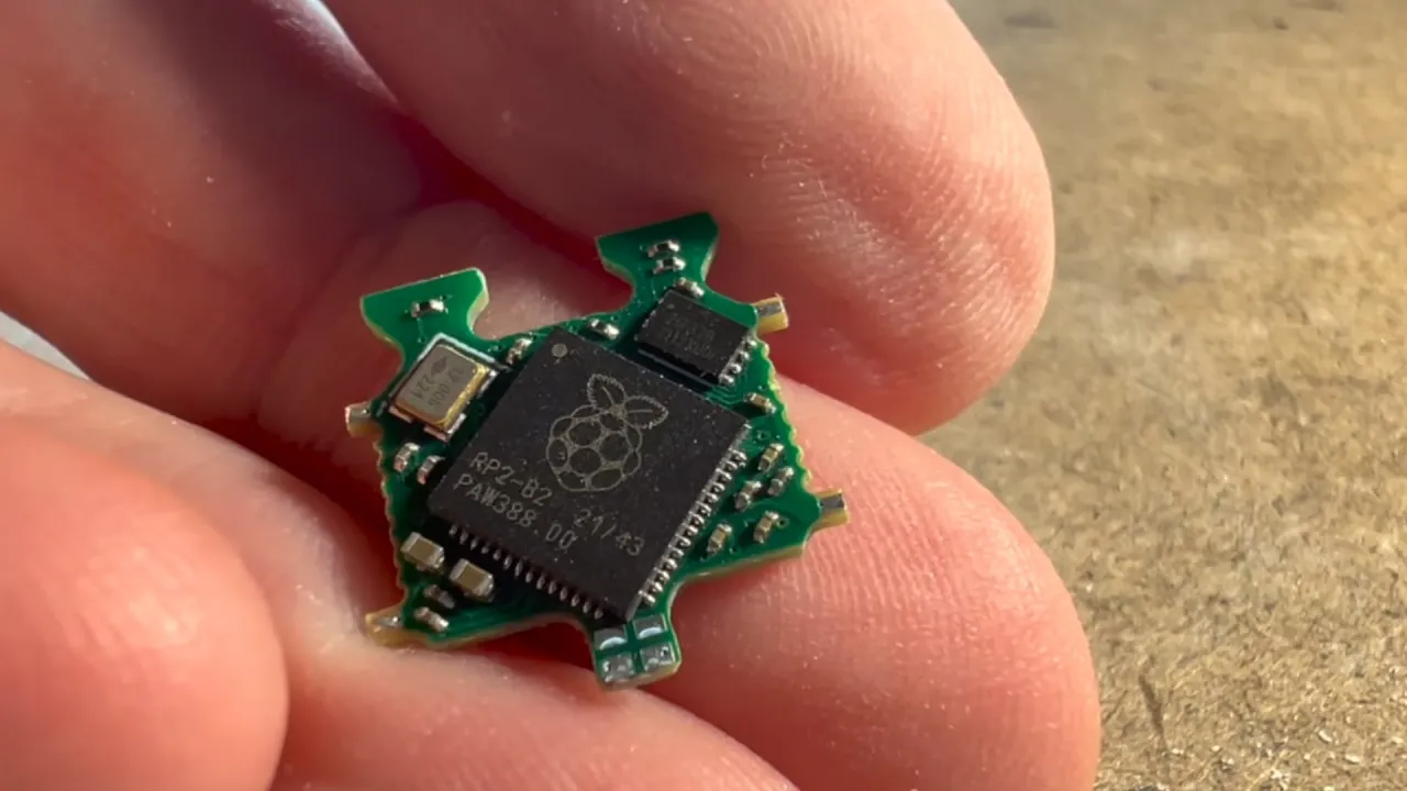
The custom circuit board designed to fit inside a standard LEGO brick form factor requires meticulous mechanical preparation before any soldering can take place. Because standard PCB manufacturing leaves a slight border of bare substrate around the perimeter, the copper traces do not run flush against the outer boundaries. Ancient notes the physical limitation directly while preparing the miniature board: “The copper doesn't go right to the edge of the board, so I need to clean it up a little.” Carefully abrading and cleaning the edges allows the compact components and edge-routed connections to sit as tightly as possible within the tight confines of the toy brick casing.
[02:12](https://www.youtube.com/watch?v=6wBrOV2FJM8&t=132s) Surface-Mount Soldering and Reflow
Once the board outline is trimmed and prepped, the assembly shifts to mounting the micro-components and display circuitry under magnification. Working at this scale requires a multi-stage soldering process to prevent parts from shifting out of alignment. Ancient begins applying chemical aid, stating simply, “Flux...” before tacking down the microscopic passives and integrated circuits. To prevent parts from blowing away or migrating across pads during final heating, Ancient explains his technique: “Dabs of solder to hold everything in place.”
After securing the components with preliminary solder anchors, the board undergoes a hot-air reflow pass. Ancient describes the goal of this thermal pass as being to “...then reflow it and make it neat,” letting surface tension pull every resistor, capacitor, and microcontroller pin cleanly onto its respective pad without bridging.
```mermaid flowchart LR accTitle: PCB Assembly and Reflow Process accDescr: Step-by-step workflow showing PCB edge preparation through reflow soldering. subgraph Prep ["Preparation"] A["Trim & clean board edges"] --> B["Apply flux"] end subgraph Solder ["Component Placement"] B --> C["Tack components with dabs of solder"] C --> D["Hot-air reflow & cleanup"] end ```
[03:46](https://www.youtube.com/watch?v=6wBrOV2FJM8&t=226s) Bodge-Wiring the Accelerometer
Even with a dedicated board layout, late design revisions require manual intervention on the hardware. An orientation sensor had to be retrofitted into the circuit after the original layout was already committed to copper. Ancient explains the retrofit: “The accelerometer was a late addition and needs some thin wires to connect up.” Using ultra-fine enamel-coated magnet wire (bodge wire), individual leads are soldered by hand from the microscopic sensor pads directly to the appropriate microcontroller traces. During this delicate assembly work under the iron, an abrupt, playful pop or burst interrupts the process with an exclamation of “*pow*” as the circuit elements are nudged into place.
- The display integrated into the build is a tiny 0.42-inch OLED panel capable of rendering greyscale imagery. - The bodge wires allow the retrofitted accelerometer to integrate with the host processor without requiring an entirely new board fabrication run.
[07:48](https://www.youtube.com/watch?v=6wBrOV2FJM8&t=468s) Mold Preparation and Resin Ingress Prevention
With the electronics, screen, and wiring fully verified and functioning, the assembly moves to encapsulation. The completed electronic core is seated inside a silicone casting mold shaped like a classic building brick. A primary hazard during liquid resin casting is the potential fouling of the female USB port, which must remain open and functional for power and data programming. To seal off the connector cavity against capillary leakage, Ancient coats the opening, remarking, “Adding some vaseline to the mould, to stop resin getting into the USB port.” The petroleum jelly forms a temporary hydraulic dam that resists the liquid polyurethane or epoxy without damaging the internal electrical contacts.
```mermaid flowchart TD accTitle: Encapsulation and Casting Workflow accDescr: Process of protecting the port, casting in resin, and curing the brick. subgraph MoldPrep ["Mold Setup"] A["Apply petroleum jelly to USB port"] --> B["Seat electronics in brick mold"] end subgraph Casting ["Resin Pour & Cure"] B --> C["Pour liquid casting resin"] C --> D["Timelapse of curing phase"] D --> E["Demold finished brick"] end ```
[09:12](https://www.youtube.com/watch?v=6wBrOV2FJM8&t=552s) Timelapse Curing and Resin Demolding
The curing phase of the encapsulation process is captured via an accelerated sequence labeled simply “Timelapse.” Over the course of the cure, the liquid mixture hardens into a solid, transparent brick, encasing the 0.42" OLED display, board, and retrofitted sensor into a permanent block. Upon inspecting the demolded piece under the workshop lights, a distinct visual shift in the cast polymer is immediately apparent, prompting Ancient to observe: “It changed colour!” The finished brick emerges as a fully self-contained microcomputer capable of driving dynamic graphics and running classic software directly on its tiny embedded screen.
## Mentioned Ancient, LEGO, Doom, uGrey, AliExpress
## Video description The making of a computer-in-a-brick.
I've chopped out sections that went on a bit, but tried to leave in enough of everything to show the whole process.
Edited together from a few different builds, so there's some continuity errors with the resin colour at the end.
Code for driving the screen in greyscale is here: https://github.com/AncientJames/uGrey The screen is a 0.42" OLED, available from aliexpress or similar. Yes it runs Doom. https://www.youtube.com/watch?v=TJHSMpYi8bg
[Source](https://www.youtube.com/watch?v=6wBrOV2FJM8)