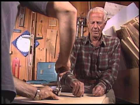
John Dobson Builds Low-Cost 16-Inch Telescope From Surplus Glass
Dobson Astro-Initiatives
Amateur observers can bypass costly commercial optics by hand-grinding surplus plate glass and building scrap-plywood mounts to produce deep-sky telescopes with optical surfaces true to sub-wavelength tolerances.
Amateur telescope makers can craft large Newtonian reflectors using accessible materials like surplus marine porthole glass, cardboard Sonotubes, and plywood mountings to dramatically outperform small commercial refractors in light-gathering power. (0:02)
Mirror fabrication requires four successive stages—rough grinding, fine grinding, pitch lap polishing, and figuring—achieving surface tolerances within 1/1,000th the thickness of plastic kitchen film. (2:51)
The classic Dobsonian mount achieves smooth, balanced alt-azimuth tracking through gravity-assisted friction mechanics, employing Teflon pads riding against materials like computer hard drive platters and phonograph records. (47:55)
Optical testing and figuring can be carried out without complex laboratory instruments by star testing on sunlight reflected from distant insulators to evaluate and correct inside- and outside-of-focus diffraction discs. (80:03)
Detailed notes
## Background
Published on YouTube by Dobson Astro-Initiatives on December 9, 2014, this instructional guide features renowned amateur astronomer John Dobson demonstrating the step-by-step construction of a Dobsonian telescope. The presentation details both the optical mirror-making process and the low-cost mechanical assembly of the mount and tube.
## TL;DR
John Dobson guides viewers through fabricating a large-aperture Newtonian reflector telescope from surplus materials, beginning with rough grinding, fine grinding, and pitch-lap polishing a 16.5-inch porthole glass blank. He demonstrates testing the optical curve using reflected sunlight and distant insulators, detailing how to figure out defects with a sub-diameter lap before sending the glass for vacuum aluminizing. Dobson then constructs the entire mechanical structure using plywood, concrete-forming Sonotube, Teflon pads, computer hard drive platters, a nine-point flotation cell, and a wooden shingle spider mount. The project concludes with optical collimation and achieving first light on the Moon, accompanied by reflections on cosmology and amateur astronomy.
## Atmosphere & style
The presentation carries the warmth, dry wit, and unpretentious wisdom of an old-school workshop masterclass. Dobson balances the grueling physical labor of mirror grinding—calling it a 'caveman's job'—with grandfatherly humor and ingenious, frugal engineering hacks. The narrative moves steadily from sweaty backyard labor to microscopic precision and quiet, starry-eyed philosophical wonder.
## Bulletin
- [00:02](https://www.youtube.com/watch?v=snz7JJlSZvw&t=2s) Amateur telescope makers can craft large Newtonian reflectors using accessible materials like surplus marine porthole glass, cardboard Sonotubes, and plywood mountings to dramatically outperform small commercial refractors in light-gathering power.
- [02:51](https://www.youtube.com/watch?v=snz7JJlSZvw&t=171s) Mirror fabrication requires four successive stages—rough grinding, fine grinding, pitch lap polishing, and figuring—achieving surface tolerances within 1/1,000th the thickness of plastic kitchen film.
- [47:55](https://www.youtube.com/watch?v=snz7JJlSZvw&t=2875s) The classic Dobsonian mount achieves smooth, balanced alt-azimuth tracking through gravity-assisted friction mechanics, employing Teflon pads riding against materials like computer hard drive platters and phonograph records.
- [01:20:03](https://www.youtube.com/watch?v=snz7JJlSZvw&t=4803s) Optical testing and figuring can be carried out without complex laboratory instruments by star testing on sunlight reflected from distant insulators to evaluate and correct inside- and outside-of-focus diffraction discs.
## Key takeaways
- [00:02](https://www.youtube.com/watch?v=snz7JJlSZvw&t=2s) Amateurs build large Newtonian reflectors rather than refractors because large primary mirrors gather exponentially more light at a fraction of the cost.
- [04:35](https://www.youtube.com/watch?v=snz7JJlSZvw&t=275s) Mirror blanks can be sourced from surplus plate glass, such as a 1-inch-thick, 16.5-inch marine porthole, requiring only sufficient thickness and roundness.
- [07:37](https://www.youtube.com/watch?v=snz7JJlSZvw&t=457s) Rough grinding with coarse 60-grit carborundum scoops out the mirror center using overhanging chordal strokes until sagitta depth approaches target thickness.
- [10:40](https://www.youtube.com/watch?v=snz7JJlSZvw&t=640s) Focal length is controlled by disk positioning: tool-on-bottom deepens the center to shorten focal length, while mirror-on-bottom grinds the outer shoulders to lengthen it.
- [16:42](https://www.youtube.com/watch?v=snz7JJlSZvw&t=1002s) Strict hygiene between grit stages, including changing work zones and thoroughly washing tools, is vital to prevent stray coarse particles from scratching finer surfaces.
- [26:06](https://www.youtube.com/watch?v=snz7JJlSZvw&t=1566s) Polishing requires a faceted pitch lap that embeds cerium oxide while slowly yielding under pressure to conform perfectly to the mirror's spherical curve.
- [30:36](https://www.youtube.com/watch?v=snz7JJlSZvw&t=1836s) Finger contact on polished optical glass must be strictly avoided because skin oils chemically etch the glass and prevent aluminum coatings from adhering.
- [35:13](https://www.youtube.com/watch?v=snz7JJlSZvw&t=2113s) Primary mirror focal length can be accurately determined prior to full polishing by measuring the radius of curvature using a flashlight and target screen.
- [47:55](https://www.youtube.com/watch?v=snz7JJlSZvw&t=2875s) The Dobsonian alt-azimuth mount utilizes Teflon pads bearing against smooth hard drive platters or records to deliver stable, diagonal glide without mechanical backlash.
- [51:50](https://www.youtube.com/watch?v=snz7JJlSZvw&t=3110s) Large, thin mirrors require kinematic flotation systems, such as nine-point triangle cells and flexible strap slings, to prevent astigmatism and gravitational flexure.
- [01:02:06](https://www.youtube.com/watch?v=snz7JJlSZvw&t=3726s) Cardboard concrete forming tubes (Sonotubes) provide rigid, lightweight optical assemblies when reinforced with internal sleeve rings and wooden boxes.
- [01:09:56](https://www.youtube.com/watch?v=snz7JJlSZvw&t=4196s) Secondary diagonal mirrors must be supported kinematically on three non-delaminating points, such as leather pads, to avoid inducing optical strain.
- [01:20:03](https://www.youtube.com/watch?v=snz7JJlSZvw&t=4803s) Sunlight reflecting off a distant power-line insulator serves as an effective artificial star to test focal convergence and reveal optical zones without a laboratory.
- [01:21:17](https://www.youtube.com/watch?v=snz7JJlSZvw&t=4877s) A persistent high center on a large mirror can be systematically dug out and corrected using a warmed, sub-diameter pitch lap without damaging the delicate mirror edge.
- [01:23:22](https://www.youtube.com/watch?v=snz7JJlSZvw&t=5002s) Accurate optical alignment is finalized by placing a center-spot decal on the primary mirror and tuning secondary spider position and tailgate collimation bolts.
## Detailed walkthrough
### [00:02](https://www.youtube.com/watch?v=snz7JJlSZvw&t=2s) The Purpose of Building Telescopes and the Reflector Design
The presentation opens with Albert Einstein’s reflection on nature: “Out yonder there was this huge world which exists independently of us human beings and which stands before us like a great eternal riddle at least partially accessible to our inspection and thinking. The contemplation of this world beckoned like a liberation.” John Dobson explains that this vast universe is precisely why people want to build telescopes—not simply to look at printed photographs, but to witness celestial wonders directly with their own eyes. Rather than building small refractors resembling a ship captain’s spyglass with a front lens, amateur telescope makers construct large Newtonian reflectors with rear mirrors to gather substantially more light.
Dobson demonstrates the anatomy of the telescope they will build. The structure is open at the front, allowing incoming light to travel down through the tube or open strut framework to a slightly curved concave primary mirror resting at the bottom. That mirror reflects the converging beam back up toward the front end, where a flat secondary diagonal mirror deflects the light outward at a right angle into the drawtube, focusing an image just below the eyepiece for viewing.
```mermaid
flowchart LR
accTitle: Optical Path of a Newtonian Reflector
accDescr: Light travels into the tube, reflects off the primary mirror to a diagonal secondary, then into the eyepiece.
A["Incoming Starlight"] -->|"Enters open front"| B["Concave Primary Mirror (Back)"]
B -->|"Converges forward"| C["Diagonal Secondary Mirror (Front)"]
C -->|"Deflects at 90°"| D["Eyepiece Image Plane"]
```
[01:35](https://www.youtube.com/watch?v=snz7JJlSZvw&t=95s) Aperture Sizes and Focal Length Fundamentals
A telescope’s resolving and light-gathering capability is governed primarily by its aperture. Dobson explains that modest 4-inch or 6-inch mirrors perform adequately for terrestrial viewing and the Moon, while 10-inch or 12-inch apertures excel at planetary observation even through urban light pollution. For faint deep-sky targets such as distant galaxies viewed under dark mountain skies, much larger apertures like 16-inch or 18-inch mirrors become necessary. For this project, Dobson demonstrates building a 16-inch reflector, noting that peering through it is optically comparable to having an eight-foot human eyeball with its pupil opened 16 inches wide.
To explain the optics, Dobson compares a simple glass lens to a concave mirror. Just as a lens refracts light to an image plane, a curved mirror gathers and converges light forward into a focal point. In both systems, the distance from the optical glass surface to the formed image plane is defined as the focal length. Generating this exact focal curve on raw glass forms the primary labor of mirror making.
- **4-inch to 6-inch aperture:** Suitable for terrestrial landscape observing and lunar craters.
- **10-inch to 12-inch aperture:** Ideal for viewing planets and operating within city limits.
- **16-inch to 18-inch aperture:** Necessary for resolving deep-sky objects and faint galaxies from dark-sky locations.
- **Focal Length:** The measured distance between the optical glass surface and the converged image plane.
[02:51](https://www.youtube.com/watch?v=snz7JJlSZvw&t=171s) The Mirror-Making Roadmap: Grinding, Pitch Laps, and Polishing
The fundamental optical process remains the same regardless of mirror diameter, though larger blanks demand substantially more manual exertion. The maker grinds a curve into the mirror blank by rubbing it over a mating glass disc (the tool) lubricated with water and silicon carbide (carborundum) abrasive grit. Once rough grinding reaches the target sagitta depth corresponding to the desired focal length, the maker progresses through sequentially finer grits of carborundum to smooth out pits and surface fractures.
After fine grinding, the glass must be polished optically smooth using a poured pitch lap rather than a mechanical buffing wheel. Warm pitch is applied to the tool, channeled into a grid of square facets, and pressed against the mirror curve so both surfaces conform identically. Because optical pitch acts as an extremely slow-yielding solid, cerium oxide polishing compound embeds directly into the pitch squares to plane down the frosted glass at a molecular level. Once fully polished, the maker tests and corrects minor optical defects—figuring the paraboloid to a tolerance finer than a fraction of kitchen film before send-off for vacuum aluminizing. As Dobson puts it: “And when the maximum defect on the curve is less than one 1,000th of the thickness of a Saran Wrap, we're ready to have it aluminized like this and put a decal on the middle to help us line up our optics.”
- **Rough Grinding:** Generates the spherical concave curve using coarse carborundum abrasives mixed with water.
- **Fine Grinding:** Smooths surface roughness through successively smaller abrasive grit sizes.
- **Pitch Lap Fabrication:** Poured tree pitch segmented into squares, conforming to the mirror's precise curve.
- **Polishing Agent:** Cerium oxide suspended in water, flowing through lap channels to polish out ground glass.
- **Optical Figuring:** Hand-correcting zonal errors until deviations are below 1/1,000th the thickness of plastic wrap.
- **Aluminizing & Centering:** Evaporative aluminum coating applied in a vacuum chamber, followed by a center spot decal for collimation alignment.
[04:35](https://www.youtube.com/watch?v=snz7JJlSZvw&t=275s) Mount Mechanics and Sourcing Raw Glass Blanks
Following optical preparation, the wood telescope tube or truss cage is mounted into an alt-azimuth rocker box. Dobson emphasizes the mechanical goal: “We want to be able to push it wherever we want it to aim and have it stay wherever we leave it.” He advises aspiring builders to source glass and supplies through classified advertisements in periodicals such as *Sky & Telescope* or *Astronomy* magazine, or by consulting local amateur astronomy clubs, where experienced builders can direct newcomers to suppliers.
For the project demonstrated on camera, Dobson uses an old surplus marine porthole blank that measures 1 inch thick at the perimeter and 16.5 inches across. Although heavy salvage portholes can be difficult to acquire, he clarifies that any sufficiently thick, round plate glass will serve as a suitable telescope mirror blank.
```mermaid
flowchart TD
accTitle: Stages of Dobsonian Construction
accDescr: Sourcing materials, grinding and polishing the mirror, and constructing the alt-azimuth mount.
subgraph Optics ["Optical Fabrication"]
G1["Rough Grinding (60 Carborundum)"] --> G2["Fine Grinding (Progressive Grits)"]
G2 --> G3["Pitch Lap Polishing (Cerium Oxide)"]
G3 --> G4["Figuring, Aluminizing & Center Spotting"]
end
subgraph Mechanical ["Mechanical Structure"]
M1["Source Glass & Hardware"] --> M2["Build Tube / Truss Assembly"]
M2 --> M3["Assemble Alt-Azimuth Rocker Box"]
end
Optics --> M2
```
[05:35](https://www.youtube.com/watch?v=snz7JJlSZvw&t=335s) Bench Setup and Initiating Rough Grinding
Dobson prepares the work area by hammering large roofing furring nails into the wooden workbench perimeter surrounding the glass tool. The nails are positioned snugly enough to prevent lateral sliding while allowing the bottom glass disc to rotate freely. Because the porthole glass is tough industrial plate, Dobson casually uses the heavy blank itself as a mallet to tap down the nails. He props up the back legs of the workbench so grinding sludge drains away from the operator, joking: “Before we actually start to grind, we want to pick up the back end of the bench so that the mud from the grinding won't run into our laps. If it runs into your lap, mommy won't like that.”
To begin rough grinding, water is splashed over the glass and sprinkled with coarse 60-grit carborundum abrasive. Dobson describes the ideal abrasive coverage as resembling “about four times salted scrambled eggs.” While an old pitch lap on the recycled tool initially muffles the sound, grinding quickly wears the pitch away, creating a loud, characteristic grinding rasp.
- **Furring Nail Clamps:** Driven directly around the glass perimeter to arrest sliding while permitting manual rotation.
- **Slurry Incline:** Elevating the bench prevents abrasive mud runoff onto the telescope maker.
- **Abrasive Distribution:** 60-grit carborundum applied generously with water across the glass interface.
[07:37](https://www.youtube.com/watch?v=snz7JJlSZvw&t=457s) Stroke Geometry and Pressure Dynamics
To grind a concave bowl into the upper blank and a corresponding convex shape into the stationary lower tool, the mirror blank must remain on top during rough grinding. Dobson overhangs the mirror off-center relative to the lower tool glass. This chordal stroke forces the dense center of the top blank to ride heavily across the outer perimeter of the bottom tool, aggressively scooping out the center of the mirror while beveling down the outer edges of the tool.
Dobson explains that carborundum cuts fastest under concentrated mechanical load. Because glass is rigid, downward force applied along the center diameter is transmitted straight through the core of the blank. Dobson deliberately plants his hands along this central chord rather than on the edges, driving rapid central glass removal until the center sagitta reaches approximately the thickness of a five-cent nickel coin. Once the abrasive grit breaks down into fine, quiet mud, cutting efficiency halts, requiring the slurry to be washed away before charging fresh grit.
> “Carborundum grinds fastest under pressure. So since this is a solid piece of glass, it behaves as if all the pressure is at the middle and I put my hands down in such a way that the pressure of my hands is on the line across the middle.” — John Dobson
[09:00](https://www.youtube.com/watch?v=snz7JJlSZvw&t=540s) Grit Hygiene, Edge Safety, and Mirror Rotation
Dobson emphasizes cleanliness and careful handling when working with abrasives. Builders must roll their shirtsleeves above the elbow to prevent coarse carborundum grains from lodging in the fabric and later contaminating fine-grinding stages. He recounts a cautionary tale from an optical workshop: “Up in Sacramento, there was a little boy who used to wipe his hands on his pants. He used to run his hands through his hair and he used to wipe his hands under his armpits and he was sparkly all over and I made him go and change his clothes and take a shower between each two kinds of grits.” Dobson also cautions against dragging the bevel of the upper mirror against the tool when lifting or setting it down, as chipping the mirror blank ruins the optical edge.
During grinding, the operator rotates the top mirror continuously to ensure a symmetrical spherical depression. The bottom tool requires only occasional turning; as Dobson explains, “diseases of the tool are not contagious to the mirror because the mirror is turning all the time on the tool.” Even if the bottom glass has edge chips, the rotating mirror averages out imperfections. Dobson concludes by defining a “wet”—the period between applying fresh abrasive and its breakdown into spent mud—and inspects the glass after completing two full wets, showing the circular frosted depression beginning to spread steadily toward the edges.
[10:40](https://www.youtube.com/watch?v=snz7JJlSZvw&t=640s) Rough Grinding Mechanics and Inverting the Glass
John Dobson demonstrates the visual advantage of beginning mirror fabrication with an already-curved tool rather than a completely flat blank. Because the tool was pre-curved, the team can visibly track the frosted grinding pattern spreading outwards toward the perimeter instead of being obscured by random, uniform pits. The primary challenge during rough grinding is coordinating depth and diameter: the curvature must reach the very edge of the mirror disk at the exact moment the desired sagitta (depth) is attained. If the center becomes too deep before the curve extends to the edge, the operator places the mirror on the bottom with the tool on top to grind down the shoulders. Conversely, if the curve hits the edge while still too shallow, the operator increases the overhang strokes to grind out the middle faster. Dobson playfully characterizes the physical exertion required at this stage: “Now, this is called rough grinding, and it's a caveman's job. You eat well, sleep well, and work like hell.”
```mermaid
flowchart TD
accTitle: Rough Grinding Position Adjustments
accDescr: Flowchart illustrating whether to place the tool or mirror on the bottom depending on focal length and edge progress.
A["Check Rough Grind Progress"] --> B{"Current Status?"}
B -->|"Center too deep / Focal length too short"| C["Mirror on Bottom, Tool on Top"]
C --> D["Grind away outer shoulders to lengthen focal length"]
B -->|"Curve hits edge too early / Center too shallow"| E["Tool on Bottom, Mirror on Top"]
E --> F["Hang mirror over edge to hollow center and shorten focal length"]
```
Dobson's grinding partner confirms they have put in roughly 9.5 hours of rough grinding so far. When they first checked the focal length, it registered between 5 and 6 feet—far shorter than their target of 8 feet. Dobson demonstrates with the glass blanks how the tool had originally been placed on the bottom with the mirror overhang stroking over the perimeter, carving out the center. To correct the excessively short focal length, they inverted the setup: placing the mirror face-up on the bottom and running the tool over the high shoulder glass for about two hours. This successfully pushed the curve outward to within a quarter-inch of the edge.
- Total rough grinding time elapsed: approximately 9.5 hours.
- Target mirror focal length: 8 feet.
- Intermediate measured focal length: between 5 and 6 feet (prior to shoulder grinding).
- Progress: curve expanded outward to approximately 1/4 inch from the mirror edge.
---
[12:41](https://www.youtube.com/watch?v=snz7JJlSZvw&t=761s) Wet Focal Length Testing and Tool Rotation Rules
To measure the focal length of a ground, unpolished mirror blank, Dobson brings the glass out onto the lawn. Because the frosted surface scatters light diffuse, pouring a sheen of water over the glass creates a temporary specular surface capable of reflecting the sun or sky to a focus. Measuring the reflected focal point with a tape measure reveals they overcorrected: the focal length now reads approximately 9.5 feet. Dobson explains that while pushing the curve outward to the edge by grinding the shoulders, they flattened the overall profile too much. To shorten it back toward the 8-foot target, they must flip the arrangement once more, placing the tool back on the bottom and the mirror on top.
Dobson also emphasizes an essential rule regarding rotation during grinding. When the mirror rests on top, it naturally turns in the worker's hands with every stroke. However, when the mirror sits on the bottom, the worker must deliberately turn it continuously. In contrast, the tool requires far less obsessive management when it is underneath. Dobson reassures his student with one of his trademark maxims: “As I so often say, diseases of the tool are not contagious to the mirror for the simple reason that they're turning with respect to each other all the time.”
---
[14:41](https://www.youtube.com/watch?v=snz7JJlSZvw&t=881s) Blending Multiple Curves to Reach the 8-Foot Target
After another bout of grinding with the tool on the bottom, the team measures the wet focal length again, finding it at 8 feet 3 inches. Holding the wet blank up level to examine the reflection of the sky, Dobson detects the optical presence of multiple distinct radii on the glass face. The deep original center curve (from when the tool was on the bottom) has an intermediate step where the shoulder was ground down (with the mirror on the bottom), leaving an unblended transition. Dobson instructs his partner to continue grinding for roughly another half-hour to remove the remaining shoulder step and blend the zones into a single uniform sphere.
A subsequent wet test shows the focal length has reached 8 feet (just an inch shy, which Dobson accepts as ideal). The curve has now pushed out to within roughly 1/16 to 1/8 inch of the mirror edge. Satisfied that 60-grit roughing has completed its duty, Dobson calls for a complete washdown and announces they are ready to transition to 80-grit silicon carbide.
- Second focal measurement: 8 feet 3 inches.
- Final 60-grit focal measurement: exactly 8 feet (or just 1 inch shy of 8 feet).
- Outer unground shoulder margin remaining: approximately 1/8 inch to 1/16 inch from the edge.
---
[16:42](https://www.youtube.com/watch?v=snz7JJlSZvw&t=1002s) Decontamination and Moving Down to 80 Grit
Dobson insists on rigorous cleaning protocols when switching abrasives. Any single rogue particle of coarse 60 grit carried forward into finer grits will leave deep gouges across the surface, ruining hours of work. He commands his partner to carry the dirty bucket away while he washes the blanks and the ground with a garden hose. The entire operation shifts physically across the grass: “This is all 60 grit part of the lawn. We'll move to another part for 80 grit.”
Dobson cleans the water bucket methodically, spraying the outside rim and grooves first so contaminated rinse water never splashes back inward. A brand-new cloth towel is broken out, strictly retiring the rag used during 60-grit grinding. Dobson also warns about personal habits, noting that shirtsleeves must be rolled up high or jackets removed completely, as coarse grit trapped in cuffs easily falls into later stages. Placing the glass together with 80 grit and water, Dobson points out a trapped air bubble between the disks. This bubble reveals that the central curve still varies minutely from the perimeter zone; however, because the difference is slight, the 80-grit run will easily bring the surfaces into complete contact without the glass seizing.
---
[18:32](https://www.youtube.com/watch?v=snz7JJlSZvw&t=1112s) Progressing through Fine Grits: 80 to 400
After grinding with 80 grit, the team re-measures the focal length on the lawn with water and a sheet of paper. The measurement sits locked at exactly 8 feet, and the curve has expanded to within 1/16 inch of the edge—close enough for subsequent stages to clean up. Dobson summarizes the abrasive progression: having finished roughing with 60 and 80 Carborundum (silicon carbide), they proceed through fine grinding with 100, 240, and 400 grits, before finishing on 1,000 grit. He critiques commercial telescope-making kits that supply 12 to 14 incremental grit grades, explaining that excessive grades needlessly multiply cleanup intervals: Dobson advocates using fewer grit sizes with roughly eight “wets” (charges of abrasive) per grade instead.
Pouring out samples of 80 grit alongside 400 grit, Dobson illustrates the drastic difference in particle size. To verify that a grit stage is truly finished, the mirror is cleaned, dried, and held up directly before a bright single light bulb with the user's eye right against the glass face. If any lingering, larger pits from the previous grit sparkle against the finer matte background, that stage must be repeated. Dobson also details a critical hydrodynamic technique used from 400 grit onward: warm water is introduced between the glass blanks to create subtle thermal expansion that flexes the faces apart slightly, preventing the mirror edges from over-grinding. He demonstrates that when first charging fine grit, the tool balances on grit mounds, but once squashed, a thick hydraulic water film forms. Grinding must proceed gently until excess water escapes the edges and the fine particles directly bite the glass.
- Grits used in Dobson's sequence: 60, 80, 100, 240, 400, and 1,000.
- Standard protocol: approximately 8 wets per grit stage.
- Inspection method: dry glass inspected against a single bright background light bulb placed directly behind the blank.
- Hydrodynamic control: warm water used from 400 grit onward to avoid excessive edge wear.
[22:08](https://www.youtube.com/watch?v=snz7JJlSZvw&t=1328s) Preventing Sticking and Introducing the Polishing Stages
During the final transitions of grinding, keeping the tool and mirror properly meshed is critical to prevent the two glass disks from seizing together. If the disks lock up completely, they can be pounded apart or soaked in a bathtub of warm water until they separate naturally on their own, though water soaking is slow. As the glass approaches center during a stroke, increased resistance serves as an immediate warning sign that sticking is imminent. Grinders must not force the stroke through when friction spikes; instead, they should pull back, add fresh grit, and work with short, fast strokes until the curves conform to one another again.
```mermaid
flowchart TD
accTitle: Grinding Sticking Prevention and Mirror Fabrication Stages
accDescr: Flowchart illustrating how to handle sticking during grinding and the four overarching stages of mirror making.
subgraph Sticking_Response["Handling Tool and Mirror Resistance"]
A["Stroke approaches center"] --> B{"Feels sticky?"}
B -- "No" --> C["Continue grinding stroke"]
B -- "Yes" --> D["Do not force stroke"]
D --> E["Back mirror off"]
E --> F["Add fresh grit & take short, fast strokes"]
end
subgraph Mirror_Stages["Four Stages of Fabrication"]
S1["1. Rough Grinding (Completed)"] --> S2["2. Fine Grinding (Completed)"]
S2 --> S3["3. Polishing with Pitch Lap"]
S3 --> S4["4. Final Figure Correction"]
end
```
The process of fabricating a telescope mirror comprises four distinct stages: rough grinding, fine grinding, polishing, and final figure correction. With the rough and fine grinding completed, the process transitions to preparing a pitch lap for polishing. While individual lap sizes vary depending on the mirror diameter, the heating and pouring demonstration accommodates an entire workshop of students building eight-inch and ten-inch telescopes.
- “If it gets sticky as you're going towards center, don't push it on over.” — John Dobson
- “In the preparation of the telescope mirror, there are four stages.” — John Dobson
---
[23:33](https://www.youtube.com/watch?v=snz7JJlSZvw&t=1413s) Heating the Pitch and Prepping the Glass
Pitch must be liquefied slowly until it reaches the consistency of cold honey before it can be applied to the glass. Approximately two standard blocks of pitch are sufficient to cast an eight- or ten-inch lap, though extra material must be factored in because a significant amount coats the inside of the heating container. Pitch cans are placed over very low flame for a couple of hours. As the material warms, liquid gathers at the bottom of the vessel; the container must be gently agitated to draw the hotter liquid up and submerge the colder solids. Allowing pitch to overheat destroys its mechanical compliance, stripping its essential ability to yield under slow pressure.
```mermaid
flowchart LR
accTitle: Surface Preparation for Pouring a Pitch Lap
accDescr: Diagram showing how mirror glass and tool glass receive opposite treatments before pouring hot pitch.
subgraph Mirror_Prep["Mirror Face (Release Surface)"]
M1["Mirror Face"] --> M2["Apply Cerium Oxide Slurry & Water"]
M2 --> M3["Result: Pitch will NOT stick"]
end
subgraph Tool_Prep["Tool Face (Adhesion Surface)"]
T1["Tool Glass"] --> T2["Coat with Turpentine"]
T2 --> T3["Result: Pitch adheres permanently"]
end
```
Preparing the glass disks requires applying opposing surface treatments so the molten pitch adheres to the tool but releases cleanly from the mirror. After collecting a small amount of paper from the restroom to clean and spread materials, the mirror face is lightly coated with water and cerium oxide. The cerium oxide must not be applied excessively—just enough to create an even, wet release barrier across the glass so the pitch will not bond to it. Conversely, the glass tool is wiped with turpentine, which ensures the poured pitch adheres firmly to its surface, even if the turpentine inevitably leaves a messy residue on the fingers.
- Pitch must reach the consistency of cold honey before pouring.
- Two blocks of pitch are generally allocated for an 8-inch lap, accounting for residual waste inside the heating can.
- Heating must be kept very low for roughly two hours to prevent scorching and degradation of the pitch's physical properties.
---
[26:06](https://www.youtube.com/watch?v=snz7JJlSZvw&t=1566s) Pouring and Grooving the Pitch Lap
Once heated, the pitch is poured onto the turpentine-treated tool. A channeling stick made of wettable, unfinished wood is soaked thoroughly in water so it will not stick to the pitch while pressing channels into the hot surface. Pouring temperature is critical: pitch poured at a cooler temperature yields a thick, substantial lap that retains heat and allows ample working time. Paradoxically, pitch poured too hot spreads out very thin; the thin layer rapidly dumps its heat into the glass below, chilling instantly and becoming too rigid to groove with the wet wooden stick.
Pouring at excessive temperatures also introduces structural failure when separating the disks. If pitch is poured too hot, the layer in contact with the cool mirror face freezes, while the layer touching the tool also freezes, leaving the middle core soft and molten. When the mirror is lifted off, this warm internal layer shears in half, tearing the lap apart and forcing the worker to scrape the pitch off with knives or forks and restart. Grooving or "waffling" the surface into distinct facets is vital: the grid pattern gives the pitch room to yield and expand laterally under slow pressure, allowing the lap to continuously conform to the mirror's precise spherical curve while embedding the polishing compound.
- “If I pour it with pitch that's too hot, the pitchlap will be very thin.” — John Dobson
- “For polishing the mirror, we need some substance like pitch that has the ability to embed the polishing agent and yet will yield under slow pressure to conform to the curve of the mirror.” — John Dobson
- When pitch splits during separation, it indicates that the outer surfaces froze against the cold glass while the center remained liquid.
---
[30:36](https://www.youtube.com/watch?v=snz7JJlSZvw&t=1836s) Wet Pressing, Dry Pressing, and Mirror Care
When a mirror rests on a freshly poured, grooved lap with cerium oxide and water between them, it is in a "wet pressed" state. If polishing is interrupted briefly—such as running out to buy beer and pet food, which Dobson jokes are the two most commonly purchased items at the grocery store—the mirror can safely sit wet pressed. However, for long breaks, overnight storage, or weekend trips, a mirror must never be left wet pressed. Over extended intervals, the water dries out, causing the cerium oxide to bond the mirror and pitch together so tightly that they cannot be separated without damage.
```mermaid
flowchart TD
accTitle: Pitch Lap Storage Protocol
accDescr: Decision flowchart showing how to store a mirror and pitch lap depending on the length of interruption.
A{"Length of Interruption?"} -->|"Short Break (e.g., store run)"| B["Leave Mirror Wet Pressed"]
B --> C["Keep cerium oxide slurry between faces"]
A -->|"Long Break (Overnight / Weekend)"| D["Convert to Dry Pressed"]
D --> E["Separate mirror and pitch lap immediately"]
E --> F["Dry mirror with clean, soft rag"]
E --> G["Let pitch lap dry completely into grooves"]
F --> H["Squeegee dust off mirror face"]
G --> I["Lower mirror dead center onto lap without sliding"]
```
For long absences, the mirror and lap must be "dry pressed." The worker separates the pair, leaves the pitch lap open to dry thoroughly down into its grooves, and immediately dries the mirror face with a clean, expendable cloth. Once the lap is dry to the bottom of its channels, any dust is squeegeed off the glass face, and the mirror is set straight down onto the lap, center-over-center, without sliding. Dobson emphasizes that the mirror and lap remain joined for the duration of the project, cautioning workers never to touch the face of the glass with bare fingers. Glass is chemically attacked by finger grease, and oily residue will prevent the aluminizing film from adhering properly later on. Reassuring his students, Dobson reminds the class that mistakes are never permanent.
- “The mirror and the pitchlap are married till the illuminizer dust them part.” — John Dobson
- “The glass is soluble in fingerprints.” — John Dobson
- “There is no boo boo that can be followed by a life of sorrow.” — John Dobson
- “If you drop your mirror and break it, you were supposed to do it the first day. If you've waited till now, you're just a fool.” — John Dobson
---
[33:16](https://www.youtube.com/watch?v=snz7JJlSZvw&t=1996s) Polishing Mechanics and Avoiding Thermal Distortion
Polishing differs fundamentally from grinding in how the abrasive interacts with the glass. In grinding, the abrasive grains roll loose between the glass faces. In polishing, particles of cerium oxide embed directly into the upper surface of the pitch facets and plane down the microscopic peaks of the glass. Because planing creates substantial drag, pushing the mirror requires considerably more physical effort. Firm downward pressure accelerates polishing, but excessive cerium oxide slurry should never be added. An overabundance of cerium oxide acts as a liquid lubricant rather than a cutting interface; only a small amount embedded in the pitch with just enough water to keep the contact zone damp is required.
Proper stroke discipline and thermal control are critical while working over the lap:
- **Lap Overhang Prevention:** The pitch lap must never be allowed to sit overhang-style over the edge of the mirror. Unlike hard grinding tools, resting an overhanging mirror edge against soft pitch indents the facets; the adjacent squares remain high, and when pushed back across the mirror, these elevated edges will gouge and groove the glass surface.
- **Thermal Spot Management:** If the surface begins drying out, warm water must never be poured directly onto the center of the lap. A localized pool of warm water heats the center of the glass disk, causing that spot to expand and elevate. Polishing over that thermally raised mound removes too much glass from the center, creating a permanent depression or hole once the mirror cools back down.
- **Slurry Application Technique:** To re-wet the lap safely, a tiny pinch of cerium oxide is placed on the surface, followed by a few drops of warm water worked off the fingertips and quickly smeared evenly across the entire face to distribute the heat uniformly.
- “Grinding we rolled over the grits. Now we're going to plane the surface of the glass and it pushes a lot harder.” — John Dobson
- “If you put on too much serium oxide in water, it serves as a lubricant.” — John Dobson
[35:13](https://www.youtube.com/watch?v=snz7JJlSZvw&t=2113s) Measuring Focal Length at the Center of Curvature
Polishing is hard physical work, and John Dobson emphasizes that you cannot allow the tool to rotate randomly: “You mustn't let it do its turning on its own hooks.” Just as in fine grinding, mirror makers must ensure the exact same amount of polishing occurs for the same amount of turning to maintain an even curve across the blank. However, even with only a light polish on the glass, the mirror reflects enough light to measure its true focal length. While an earlier estimate was made using water on the fine-ground surface, measuring the curve directly from the polished glass is critical because it establishes the precise dimensions needed to source the cardboard tube and build the telescope structure.
Dobson explains that there are two primary methods to determine focal length. The direct method uses sunlight focused to a pinpoint image. In the absence of the sun, one can treat the concave mirror as part of a giant, shiny sphere—analogous to the reflective interior of a Christmas ornament—where any light originating from the center of the sphere bounces straight back to its source. By positioning a flashlight slightly off-axis and catching the reflected bulb image on a piece of paper, moving back and forth until the filament image comes into sharp focus right next to the flashlight bulb, you locate the center of curvature. Because the radius of curvature is roughly twice the focal length, Dobson targets around 16 feet for a planned 8-foot mirror.
```mermaid
flowchart LR
accTitle: Center of curvature focal length test
accDescr: Light travels from a flashlight to the mirror and reflects back to an adjacent paper screen at twice the focal length.
subgraph TestSetup["Center of Curvature (approx. 16 ft)"]
A["Flashlight Source"]
B["Paper Target Screen"]
end
C["Polished Mirror Face"]
A -->|"Diverging light beam"| C
C -->|"Converging reflection"| B
```
- When the image on paper reaches maximum sharpness at the same distance as the flashlight bulb, the distance measured to the mirror face is the radius of curvature ($R = 2f$).
- Dobson's measurement yields 16 feet 2 inches, putting the true focal length at exactly 8 feet 1 inch (97 inches).
- Dobson approves of hitting 8 feet 1 inch when targeting 8 feet: “If the focal length is too long, the telescope is too hard to manage. If the focal length is too short, it's too hard to get high enough power.”
[39:35](https://www.youtube.com/watch?v=snz7JJlSZvw&t=2375s) Edge Polishing, Squeegeeing, and Preventing Pitch Lap Scratches
With the focal length verified, mirror makers can safely purchase the tube and build the mount, but several hours of polishing remain. Dobson points out that their mirror has a slight polish, though it remains hazy toward the outer perimeter. Many amateur mirrors fail to polish out at the edge or end up with a turned-down edge (where the figure drops too low), an error usually caused by improper fine grinding or letting tools hang over the rim. Using warm water during fine grinding helps ensure the perimeter polishes out. Dobson stresses that the perimeter represents a massive percentage of total aperture: adding just one inch of glass around the outer edge collects far more light than adding an inch in the mirror's center.
Before returning the mirror to the stand, Dobson wipes the face using a bare, dry hand like a squeegee. Cloths leave behind unseen lint, whereas clean skin can instantly feel fine grit. He applies a slurry of cerium oxide and warm water, warning that polishing by hand is demanding—commercial manufacturers use machines—and requires about four more hours depending on worker stamina: “Depends on how hard it pushes and how much we eat.” Great care must be taken never to chip pitch against the mirror blank when seating the lap:
- A full 24-inch mirror requires only about one-quarter teaspoon of cerium oxide, though builders usually apply more.
- If a chipped fleck of pitch falls onto the face, it can lodge into one of the lap's faceted squares, raising that facet and cutting a groove into the glass with every single stroke.
- When the lap starts drying out and pulling hard, lift it off, apply a dab of cerium oxide and warm water in the center, smear the water quickly across the face to prevent localized thermal shock, and gently lay the lap back down.
[43:48](https://www.youtube.com/watch?v=snz7JJlSZvw&t=2628s) Sourcing the Sonotube and Anatomy of the Dobsonian Mount
Because mirror polishing requires hours of repetitive physical labor, builders can break up the work by going out to acquire the main telescope tube. Dobson visits a building supply store to purchase a spiral-wound cardboard concrete form (commonly known as a Sonotube). Tubes of this kind are readily obtained from concrete accessories distributors or local general contractors; Dobson picks up an 18-inch diameter tube cut to 7.5 feet (with an extra scrap piece handed over by the yard worker).
Back in the shop, Dobson uses his veteran 18-inch telescope, nicknamed "the little one," to explain the structural layout of the Dobsonian mounting. For large instruments (16 inches and above), the rectangular wooden tube box extends all the way down to the rear tailgate holding the mirror cell. On smaller scopes (12 inches and under), the box does not extend the entire length; instead, the tailgate is attached directly into the bottom of the round cardboard tube. To track and point across the sky above the horizon, the instrument rests inside an alt-azimuth rocker:
```mermaid
flowchart TD
accTitle: Dobsonian alt-azimuth mount hierarchy
accDescr: Component breakdown of the telescope tube box, rocker assembly, and ground board.
subgraph TubeAssembly["Tube Assembly"]
TB["Tube Box (holds Sonotube)"]
end
subgraph RockerAssembly["Rocker Assembly (Altitude & Azimuth)"]
CB["Cradle Boards (internal bearings)"]
SB["Side Boards"]
FB["Front Board"]
BB["Bottom Board"]
end
subgraph GroundAssembly["Ground Support"]
GB["Ground Board (3 feet / tripod)"]
end
TB -->|"rests on"| CB
CB --- SB
SB --- FB
SB --- BB
BB -->|"swivels on center pin / pads"| GB
```
- **Tube Box:** Built from 3/4-inch plywood to hold nails along the edges without splitting; made approximately 3 feet long (roughly one-third the mirror's focal length). The inside diameter is oversized relative to the cardboard tube so Teflon strips can be fitted inside, allowing the Sonotube to slide smoothly for balancing.
- **Rocker Assembly:** Consists of two side boards, a front board, a bottom board, and internal cradle boards that provide the cutouts and bearing pads to cradle the tube box for altitude motion.
- **Ground Board:** Sits directly on the ground on three feet as a stable tripod; the bottom board of the rocker rests on top of it, swiveling horizontally in azimuth.
[46:32](https://www.youtube.com/watch?v=snz7JJlSZvw&t=2792s) Sizing and Building the Rocker Box
Dobson and his team begin assembling the rocker from six pre-cut boards. Material choice changes with the size and weight of the instrument: while small telescopes use standard 3/4-inch plywood throughout, heavy, long-focal-length telescopes demand rigid stock to eliminate vibration. For this instrument, they employ 1-1/8-inch flooring plywood, doubling the thickness of the ground board to eliminate flexure under the substantial load.
Accurate interior spacing is essential to ensure the tube moves freely without binding. Dobson walks through the arithmetic for sizing the rocker's interior width:
- Outside width of the tube box: 20-1/2 inches.
- Adding the thickness of the two internal cradle boards brings the measurement to 22 inches.
- Adding a 1/2-inch operating clearance establishes an inside rocker width of 22-1/2 inches.
With the bottom board positioned on the worktable, the team prepares to dry-fit the cradle boards and the tube box to verify that the clearances match their design calculations before final fastening.
[47:55](https://www.youtube.com/watch?v=snz7JJlSZvw&t=2875s) Ground Board, Teflon Bearings, and the Azimuth Disk
John Dobson demonstrates the construction of the ground board, checking clearances against the rocker box to ensure about half an inch of clearance on the far side. He explains that the base is fundamentally a tripod despite its low profile. It stands on three feet: two placed at the front corners and one centered along the back edge. The azimuth bearing consists of three Teflon pads attached directly to the ground board, upon which a hard disk will glide. For smaller telescopes, such as eight-inch models, phonograph records serve well as the bearing surface, but for larger instruments, Dobson strongly favors computer hard drive platters. These platters measure 14 inches across, providing an exceptionally hard and slick gliding surface.
```mermaid
flowchart TD
accTitle: Azimuth Bearing Architecture
accDescr: Diagram showing the ground board tripod base, Teflon pads, and inverted hard drive platter bearing under the rocker box.
subgraph GroundBoard["Ground Board (Tripod Base)"]
F["3 Support Feet (2 Front, 1 Rear)"]
T["3 Teflon Pads (Equilateral Triangle over Feet)"]
end
subgraph RockerBox["Rocker Box Base"]
D["14-Inch Computer Hard Disk Platter (Faces Downward)"]
P["Center Pivot Bolt & Washer"]
end
GroundBoard --- RockerBox
T -.->|"Slick Bearing Contact"| D
```
Dobson emphasizes the critical orientation of the bearing components to protect them from environmental grit. The smooth platter is fastened securely with small tacks to the underside of the rocker box so that its shiny face points downward, while the stationary Teflon pads face upward on the ground board. “If we put our bearing the other side up with this up, then dirt would get on here and get into our bearing,” Dobson warns. In positioning the Teflon pads, he uses the 14-inch disk as a tracing guide. Rather than centering the circle on the geometric middle of the wooden board, he deliberately centers it directly over the triangle defined by the three ground feet to transfer the telescope's weight efficiently without inducing board flexure. The Teflon squares are arranged along the disk's perimeter in an approximate equilateral triangle and tacked down, ensuring the nail heads are driven deep beneath the sliding surface so they cannot scratch the disk. Once the central pivot bolt and washer are adjusted through both boards to just the right tension—neither loose nor overly tight—the movement glides effortlessly. “Wow, that's beautiful,” someone remarks as it spins. “That is really smooth.”
- The rocker box base clearance is gauged to roughly 0.5 inches.
- The ground board rests on three feet arranged as a tripod (two front corners, one centered in back).
- 8-inch telescopes commonly utilize vinyl phonograph records, whereas larger builds use 14-inch computer hard drive platters.
- Three Teflon pads form an equilateral triangle directly aligned over the ground board's support triangle.
- Tacks securing the Teflon must have their heads countersunk below the pad surface to avoid gouging the aluminum platter.
---
[51:50](https://www.youtube.com/watch?v=snz7JJlSZvw&t=3110s) Mirror Flexure and the Nine-Point Flotation Cell
Addressing the primary mirror, Dobson dispels the common misconception that a massive, thick glass blank is rigid enough to support its own weight without optical distortion. Even slight gravitational sag will ruin the wavefront. “You might think that a big thick piece of glass like this wouldn't bend,” Dobson explains, “and that's why they made it big thick like this, so that it wouldn't bend. But we're only allowed to bend about 1/1,000th of the thickness of a Saran Wrap.” Because permissible surface deformation cannot exceed roughly one-thousandth the thickness of plastic wrap across the full diameter, mirror cells require multi-point flotation suspensions: simple three-point supports for small, stiff mirrors, and nine-point or larger flotation cells for wider or thinner blanks.
Dobson lays out a nine-point tailgate design for this mirror. Three heavy collimation bolts pass through the tailgate to align the optical axis with the tube front. Each bolt bears against a pivoting triangular plate, and each triangle provides three contact points against the back of the glass, yielding nine balanced pressure points in total. To establish the cell layout, Dobson snaps diagonals to find the precise center of the square tailgate board. He consults a reference diagram drawn on an envelope at half scale, where an 8-inch span represents 16 inches full scale. Measuring out 2.5 inches on the drawing establishes a 5-inch radius for the circle upon which the three collimation bolt holes are drilled. Dobson stresses that the adjustment bolts must fit very snugly in their threads: “We want them tight fit so that at the star party people won't come up behind and wind them up with their fingers.”
- Mirror bending tolerance: approximately 1/1,000th of the thickness of plastic wrap across the entire diameter.
- Suspension comparison: 3-point support for small, rigid mirrors; 9-point suspension (three triangles bearing on three collimation bolts) for larger mirrors.
- Flotation geometry: calculated at half-scale (2.5 inches on paper equals a 5-inch bolt circle radius on the actual tailgate).
- Tight thread tolerances on collimation bolts prevent bystanders at public star parties from accidentally spinning them out of alignment.
---
[55:21](https://www.youtube.com/watch?v=snz7JJlSZvw&t=3321s) Flotation Triangles and the Tailgate Hinge Assembly
To assemble the flotation cell, Dobson glues a thin, flexible sheet of cardboard down to the center of the tailgate. This cardboard acts as a soft locating web: it holds the three wooden flotation triangles in their correct rotational positions without restricting their freedom to tilt and equalize pressure against the glass. Dobson notes, “The cardboard has to be thin enough so that it won't change the pressure on these on the points on the triangles.” Hard Masonite contact pads on the triangles distribute the load, cushioning the glass so that sudden shocks or drops cannot shatter the mirror against the steel bolt heads.
Wooden guide blocks are then mounted to the tailgate to establish lateral containment for the primary mirror. Measuring between the inner faces of these blocks yields roughly 16-3/4 inches, providing sufficient clearance for the mirror to slide smoothly into place while keeping it laterally centered over the flotation cell. Dobson cuts a cardboard safety bib and tapes it in place. To ensure the glass aligns perfectly over the support system once installed, the team projects the diagonal intersection lines of the tailgate through to the face of the bib. Strong metal hinges are screwed to the bottom edge of the tailgate and fastened directly to the tube box, allowing the entire rear cell to swing open for mirror maintenance and transport. Watching the heavy fastening work, Dobson jokes: “You remind me of my friend in Sacramento. By the time he finished building something, it was the weight was about half nails and half wood.”
- A thin cardboard membrane retains the three wooden triangles laterally while permitting uninhibited rocking motion.
- Protective Masonite pads buffer the mirror glass from the adjustment bolt tips.
- The span between lateral containment blocks measures approximately 16-3/4 inches, centering the mirror over the cell.
- The bib and tailgate centers are verified by intersecting corner-to-corner diagonal lines.
- Heavy-duty hinges secure the tailgate to the rocker-box lower section.
---
[58:49](https://www.youtube.com/watch?v=snz7JJlSZvw&t=3529s) Securing the Mirror: Sling Strap, Safety Hasp, and Friction Mount
With the tailgate mounted, the assembly is propped up so the mirror can be installed and secured. To guard against accidental release during handling, a safety hasp is positioned over the center joint to lock the hinged tailgate shut even when the main fastening screws are removed. Dobson inspects the glass blank, noting with amusement that the swirl of machining scratches worn into the back from the grinding stand conveniently pinpoints the exact optical center without any measuring.
A continuous webbing sling strap supports the downward weight of the mirror when the telescope points toward the horizon. Dobson fastens one end of the strap to a wooden side block, wraps it snugly under the mirror's lower circumference, pulls it taut, and fastens the opposite end before trimming away excess strap. He points out a subtle mechanical caution: “Had we left room for it, it would be better to have the strap come around the outside edges of the block. Otherwise, there's the danger that the strap itself may bend the mirror.”
Dobson then clarifies the physics of securing the strap with wood screws. The screws must have wide, washer-style heads to clamp the material firmly against the wooden block. He explains that the physical weight of the mirror cannot be allowed to pull directly against the screw shanks as a shear pin: “You see, the weight of the strap can't hang on the screw. It has to hang on the friction between the screw head and the wood.” Once the sling is clamped, the mirror is fully restrained from downward and lateral drift, leaving only the front retaining clips to be constructed to keep the mirror from tilting out forward when pointing near the horizon.
- A safety hasp keeps the tailgate locked in place as a fail-safe whenever adjustment screws are backed out.
- Swirl patterns on the back of the mirror from grinding serve as an immediate visual marker for center alignment.
- The mirror's edge rests directly in a woven belt sling anchored to the side blocks.
- The mirror's hanging load is supported through broad screw-head clamping friction against the wood, rather than bearing directly on the screw shanks.
- Forward retaining clips are required next to stop the primary mirror from tipping forward out of the cell.
[01:01:08](https://www.youtube.com/watch?v=snz7JJlSZvw&t=3668s) Mirror Retention, Tailgate Clearance, and Teflon Sliders
John Dobson inspects the mirror box mechanism, explaining the need for a physical stop to keep the primary mirror secure during transport and operation. A protruding strip, such as a piece of Masonite, must reach across the front so the mirror cannot roll out. He demonstrates the mechanical geometry: if the retainers are oriented to slide the mirror in easily, they strike the tailgate and prevent it from latching. However, rotated into position, they secure the mirror while clearing the closed door. To control the travel of the optical tube assembly, wooden stop blocks are installed inside the box frame to arrest the tube at the proper depth.
To ensure the heavy cylindrical tube can be moved smoothly for balancing without binding, Dobson installs four strips of Teflon along the internal contact surfaces of the box cradle. These pads allow the tube to slide in and out with minimal effort while maintaining a snug fit. As John Dobson summarizes the objective: “We want it so that it slides in and out easily but stays tight.”
[01:02:06](https://www.youtube.com/watch?v=snz7JJlSZvw&t=3726s) Peeling the Tube Lining and Sizing Internal Reinforcements
With the Teflon strips mounted, Dobson turns his attention to the Sonotube cardboard tube. Concrete forming tubes are manufactured with a thin internal plastic barrier to prevent moisture loss during cement curing, but this slick film must be removed before the telescope tube can be painted or glued. Grabbing a loose edge at the rim, Dobson demonstrates how to pull the plastic out in a continuous spiral sheet, warning with a dry grin about the perils of tearing: “And if it breaks, you may have to send a kid in to fix it.”
```mermaid
flowchart TD
accTitle: Tube Reinforcement Calculation Flow
accDescr: Steps to calculate the strip cut needed to sleeve a reinforcing ring inside the main tube.
A["Wall thickness: ~0.25 in"] --> B["Two walls reduce inside diameter: -0.5 in"]
B --> C["Circumference reduction = π × 0.5 in"]
C --> D["Cut strip: slightly over 1.5 in width"]
```
Dobson prepares cardboard reinforcement collars cut from spare tube sections to double the wall thickness at high-stress points—specifically at the tailgate where the tube presses upward against the box roof, and at the front where it overhangs the rocker. Sizing an outer tube section to fit snugly inside requires reducing its circumference:
- Tube wall thickness is measured with a pocket ruler at almost exactly $1/4\text{ in}$.
- Nesting the sleeve reduces internal diameter by $2 \times 1/4\text{ in} = 1/2\text{ in}$.
- Circumference reduction equals $\pi \times 0.5\text{ in}$, requiring a lengthwise slice slightly larger than $1\frac{1}{2}\text{ in}$ cut out of the ring.
- Once slit and compressed, the reinforcement ring is pressed inside the tube until it seats firmly against the stops.
[01:04:53](https://www.youtube.com/watch?v=snz7JJlSZvw&t=3893s) Building the Friction-Fit Cardboard and Brass Focuser
Dobson demonstrates his low-cost, smooth-motion focuser design, which avoids expensive rack-and-pinion hardware. The drawtube is a length of brass tubing that slides directly inside a fitted cardboard sleeve, which is glued to a curved wooden mounting block that attaches to the telescope tube wall. To achieve the correct friction on the drawtube, layers of paper can be peeled out of the cardboard sleeve if the fit is too tight, or shims glued inside if it runs loose.
When mounting the paper tube to the wooden flange, Dobson emphasizes thorough glue penetration. Rather than merely applying a bead of glue, he vigorously works the adhesive into the porous cardboard fibers with a finger. As John Dobson warns: “Because if you don't get the cardboard wet with the glue, your glue joint may not hold.”
[01:06:21](https://www.youtube.com/watch?v=snz7JJlSZvw&t=3981s) Constructing the Three-Vane Shingle Diagonal Spider
To position the diagonal (secondary) mirror in the exact optical center of the tube, Dobson constructs a three-vane spider using wooden shingles radiating outward from a central diagonal holder block. The assembly reflects light coming up from the primary mirror outward at a 90-degree angle toward the lateral eyepiece tube. Rather than gluing the shingles permanently into the central block, Dobson insists on a friction-fit tongue-and-groove joint:
> “We're not going to glue this thing in here because the way these things go to pieces is to have somebody with ice cream on his hands or her hands reach in here and pull this thing out and then the shingles get broken.”
Permanent glue turns a public outreach mishap into a field catastrophe, whereas a press-fit allows quick repair: “Now, if you've had them glued in there and they've been broken off, you're in big trouble in the in the star party site.” Dobson shapes the butt ends of the shingles with tin snips using a slight twist to produce a concave cut. This ensures the wood contacts the central block only at the outer edges, preventing the vanes from rocking or shifting out of collimation.
- The telescope tube has an inside diameter of 18 inches, requiring each vane to extend exactly 9 inches outward from the center point.
- Dobson locates the center where the three vanes converge, marks a 9-inch radius onto each shingle with a ruler, and snips off the excess.
- The outer square corners of the wooden shingles are clipped off at an angle so they will not split or bind against the cardboard tube wall when slid axially for optical alignment.
[01:09:56](https://www.youtube.com/watch?v=snz7JJlSZvw&t=4196s) Three-Point Leather Secondary Mirror Mount
Mounting the secondary mirror requires isolating the optical flat from mechanical strain. Dobson uses three small pads of leather rather than cardboard or foam. Leather is lint-free and will not delaminate under shear stress over time, preventing catastrophic mirror drops.
Dobson dispels the notion that a thick secondary flat is too rigid to flex under uneven mounting pressure. Because optical surfaces require precision down to fractions of a wavelength of light, the secondary must sit on exactly three kinematic points. As John Dobson points out: “You might think that that's too thick to bend, but we're allowed to bend at only one 1,000th of the thickness of a Saran Wrap.” Dobson applies glue to three spots on the beveled wood block, thoroughly wets both sides of the leather pads with glue, places the mirror down onto the pads, and leans the assembly upright to cure.
[01:11:30](https://www.youtube.com/watch?v=snz7JJlSZvw&t=4290s) Calculating Focuser Placement and Cutting the Port
Dobson calculates the position for the focuser port based on the primary mirror’s measured focal length of 8 feet 1 inch (97 inches). The goal is to bring the focal plane roughly $1\frac{1}{2}$ to 2 inches outside the tube wall so eyepieces can reach focus comfortably in the drawtube:
```mermaid
flowchart LR
accTitle: Optical Distance Calculation to Eyepiece Port
accDescr: Calculation showing how the 11-inch radial offset is subtracted from total focal length to locate the focuser port.
A["Primary Focal Length: 97 in (8 ft 1 in)"] --> B["Radial offset from axis: 11 in"]
subgraph OffsetBreakdown ["Offset Components"]
C["Tube center to wall: 9 in"]
D["Wall to focal plane: 2 in"]
C --- D
end
B --> E["Focuser Hole: 86 in from primary mirror"]
```
Dobson marks the focuser location on the side of the tube that accommodates natural body mechanics during sidewalk observing, allowing the user to guide the telescope with their right hand at the mouth of the tube while keeping their eye stationed at the eyepiece. To cut the hole through the Sonotube wall without tearing or fraying the laminated paper layers, he drills and chisels partially from the exterior, then stops and completes the cutout from the inside surface outward with light, rapid cuts.
[01:13:45](https://www.youtube.com/watch?v=snz7JJlSZvw&t=4425s) Balancing the Telescope and Mounting the Bearings
John Dobson begins fitting the optical assembly into the tube so the telescope can be balanced and tested. He slides the spider mount into the front of the tube until, looking down the drawtube of the eyepiece holder, the diagonal flat mirror reflects the primary objective mirror directly centered in the view. Once the diagonal is roughly set, the primary mirror is placed in the bottom end. Before the altitude bearings can be mounted permanently, the entire optical tube assembly must be balanced to determine its center of gravity. Taking the tube outside, Dobson balances it across a roller to find the tipping point. Measuring from the tailgate to the roller on both sides of the box yields 24½ inches on one side and 25 inches on the other, establishing the true center of gravity at 24¾ inches from the tailgate.
```mermaid
flowchart LR
accTitle: Determining Telescope Balance and Mount Placement
accDescr: Sequence showing optical pre-alignment, finding the center of gravity, and calculating clearance for the cradle boards.
subgraph Balance ["1. Finding Center of Gravity"]
A["Roll tube over roller"] --> B["Measure balance points:<br/>24.5 in & 25 in"]
B --> C["Average center of gravity:<br/>24.3/4 in from tailgate"]
end
subgraph Clearance ["2. Rocker Box Placement"]
C --> D["Account for corner swing radius:<br/>26.5 in total clearance"]
D --> E["Offset cradle boards:<br/>10.5 in from front wall"]
end
```
Dobson notes that the tube cannot simply pivot at exactly 24¾ inches because the swing clearance to the rear corner of the rocker box demands additional height, measuring approximately 26½ inches from the corner mark. With that clearance verified, the builders prepare to mount the cradle boards inside the rocker box. Half the width of the box is 10¼ inches, so Dobson sets the center of the cradle boards 10½ inches back from the front wall to keep the square box from striking the front panel when swung downward. Working in tandem with his assistant, screws are started from the outside while Dobson sights the altitude alignment and guides the forward-and-backward positioning.
- Center of gravity measured: 24½ inches on one side, 25 inches on the other, averaging to 24¾ inches from the tailgate.
- Swing radius to clear the rear corner: 26½ inches.
- Cradle board placement: Centered 10½ inches back from the front wall (half-width of box is 10¼ inches).
---
[01:16:32](https://www.youtube.com/watch?v=snz7JJlSZvw&t=4592s) Testing Mount Movement and Securing the Tailgate
The tube is carefully lowered onto the Teflon pads of the rocker box to verify its balance and friction. Dobson checks whether the side bearings are riding cleanly on the Teflon and tests the feel of the altitude and azimuth motion together. The response is smooth and steady; Dobson emphasizes that moving the scope diagonally should produce an immediate, simultaneous response on both axes rather than binding or sticking on one axis first. As Dobson observes:
> “When we push it on the diagonal, we want it to go on the diagonal.”
The assistant notes that the motion feels so easy that it shouldn't move any more freely, and Dobson agrees that the friction is tuned just right. The tube dips smoothly past the horizontal plane, though Dobson points out that large aperture telescopes never actually need to point down to the true horizon under ordinary observing conditions.
With the motion confirmed, the tailgate must be firmly locked down before reading the mirror's figure. While a simple latch or hasp works fine for opening and closing the tailgate when loading the glass, it cannot provide the structural rigidity required during operation and testing. Dobson drives screws into all four corner blocks so that the tailgate and the wooden box act as a single, unyielding unit. As Dobson explains:
> “You want the thing like to behave like one piece of stuff.”
Locking down the four corners stabilizes the back end completely, making it possible to collimate the primary mirror with the tailgate adjustment bolts—an impossible task if the tailgate were allowed to flex or shift.
---
[01:18:18](https://www.youtube.com/watch?v=snz7JJlSZvw&t=4698s) Collimating the Optics for the Star Test
With the tailgate rigidly secured, Dobson uses a wrench to carry out a preliminary collimation of the optical train so the unaluminized mirror can be tested outdoors. Sighting down the empty eyepiece drawtube, he checks the mechanical centering of the diagonal flat, shifting its mounting bar slightly forward so the diagonal sits directly under the drawtube axis. Looking into the drawtube, one observes the reflection of the diagonal centered against the surface of the primary mirror.
Dobson demonstrates how shifting the wooden spider's rear mounting bar steers the optical reflection: moving the bar up pushes the reflection up, pushing it down shifts the reflection down, moving it inward brings the reflection inward, and pulling it outward moves the reflection outward. Once the diagonal is centered, Dobson inspects the annular space around the reflection of the primary mirror. Noting that the reflection is asymmetric and visibly wider on one side, he instructs his helper to make tiny, incremental turns on the tailgate collimation bolts, warning him to tighten the top bolt just a hair—half as much as the previous adjustment—until the primary mirror reflection is concentric and ready for testing.
---
[01:20:03](https://www.youtube.com/watch?v=snz7JJlSZvw&t=4803s) Star Testing the Mirror Curve on an Insulator
To evaluate the optical figure of the bare glass, the builders aim the telescope at a bright glint of sunlight reflected off a distant power-line insulator, using it as an artificial star. Dobson brings the pinpoint glint to sharp focus in the eyepiece, then racks the drawtube slightly inside of focus and slightly outside of focus to observe the resulting diffraction discs. By analyzing how light is distributed across these two out-of-focus discs, any optical errors in the paraboloidal curve can be diagnosed directly. As Dobson explains:
> “Any portion of the mirror that bundles too much light beyond focus is too flat. Any part that bundles too much light on the inside disc is too deep.”
If a mirror is ground and polished too deep in the center, the rays from the central zone converge too quickly and bundle ahead of the focal point, causing the center of the inside-of-focus disc to appear bright. Conversely, if the center is too flat, central light bundles farther back, producing a prominent bright spot in the middle of the outside-of-focus disc. By alternating between pushing the drawtube in and pulling it out, Dobson reads the relative brightness across the expanded discs to assess precisely where glass needs to be removed.
```mermaid
flowchart TD
accTitle: Optical Star Test Interpretation
accDescr: Diagram explaining how inside and outside of focus light distributions reveal high or low zones on a telescope mirror.
Focus["Point-source glint in focus"] --> Inside["Racked Inside of Focus"]
Focus --> Outside["Racked Outside of Focus"]
Inside -->|"Center is overly bright"| TooDeep["Center is too deep / steep<br/>(bundles rays too early)"]
Outside -->|"Center is overly bright"| TooFlat["Center is too flat / high<br/>(bundles rays too far out)"]
```
---
[01:21:17](https://www.youtube.com/watch?v=snz7JJlSZvw&t=4877s) Correcting the High Middle with an 8-Inch Pitch Lap
The test in the backyard reveals that the 16-inch mirror has a high center—meaning the middle is too flat and failing to focus light early enough. To hollow out the center without touching or endangering the delicate outer figure, Dobson retrieves an 8-inch pitch lap. He warms the lap gradually in a bath of hot water to avoid cracking the brittle pitch, heating it slowly until a fingernail can easily indent the facets. He then presses the softened lap directly onto the 16-inch blank so that its individual squares conform exactly to the mirror’s concave curve rather than the tool’s original curvature.
```mermaid
flowchart TD
accTitle: Correcting a High Mirror Center
accDescr: Step-by-step procedure for adapting a smaller pitch lap to polish down a high center zone.
A["Heat 8-inch pitch lap slowly in warm water"] --> B["Test pitch softness with fingernail press"]
B --> C["Press softened lap onto 16-inch curve to conform"]
C --> D["Polish center until glass feels warm"]
D --> E["Re-test out-of-focus discs in tube"]
E -->|"Still too high"| D
E -->|"Discs match inside & outside"| F["Ready for aluminizing"]
```
Dobson explains that cutting down a full-sized lap is an option if a sub-diameter lap is unavailable, but doing so destroys the larger tool needed for final smoothing. Using an 8-inch grinding tool and pitch lap on larger mirrors (including 10-inch and 16-inch blanks) is standard practice because polishing almost inevitably leaves the center high. Polishing with a smaller tool allows the optician to dig out the central zone safely without rolling or damaging the mirror's edges. Dobson works the center of the 16-inch mirror with the 8-inch lap until the center of the blank feels noticeably warm to the touch. The mirror is returned to the telescope tube and re-tested on the insulator glint. Because the center remains slightly high, Dobson repeats the warming, polishing, and star-testing sequence several times. As Dobson states:
> “We had to do it several times before the out of focus discs look the same on both sides of focus. When they do, your mirror is ready for the illuminizer.”
---
[01:23:22](https://www.youtube.com/watch?v=snz7JJlSZvw&t=5002s) Aluminizing the Mirror and Center Spotting
With the curve confirmed, the mirror is readied for coating. Dobson notes that most amateur telescope makers ship their mirrors to professional coating services advertised in astronomy magazines, but in this instance, they take the glass directly to a coating facility. The mirror is soaked in an acid bath, rinsed thoroughly with water, and cleaned with pure methanol to strip all grease and contaminants before being placed inside the vacuum chamber. Inside the chamber, the turntable is spun to verify mechanical clearance, the chamber is sealed, and the vacuum pumps are turned on. Dobson remarks with enthusiasm:
> “See, this is the fun part of making telescopes. Getting the mirror illuminized. That's the fun part. You've done all your hard work. Now you get to see something.”
Once coated and retrieved, the reflective surface looks bright and clean. To ensure accurate optical collimation in the field, Dobson places a center-spot decal at the exact measured geometric center of the primary mirror. With the mirror installed, the secondary diagonal struts are adjusted until the center decal appears dead-center down the optical axis of the eyepiece drawtube. Only after this critical visual alignment is confirmed are the diagonal struts glued permanently to the interior walls of the telescope tube. With the mirror coated and the secondary locked in place, the builders prepare to assemble the completed instrument for a public star party to show observers the Moon and the universe beyond.
- Surface cleaning sequence: Acid soak, water rinse, followed by methanol wipe-down.
- Alignment aid: Adhesive decal applied to the measured center of the primary mirror.
- Spider fixation rule: Secondary struts are glued permanently to the tube only after being visually aligned to the primary's center decal through the drawtube.
[01:26:09](https://www.youtube.com/watch?v=snz7JJlSZvw&t=5169s) Final Collimation and Installing the 16-Inch Mirror
The newly aluminized 16-inch primary mirror is brought out and mounted into the cell, eliciting sheer awe from the builders as its gleaming reflective surface is unveiled: “My golly, that is incredible.” Dobson explains that during earlier testing and rough construction, the diagonal secondary mirror had only been aligned rather crudely. With the mirror now freshly coated and a center decal marking its exact optical center, they can achieve precise optical alignment.
Looking through the focuser, Dobson directs the fine-tuning of the diagonal mirror until the primary's center decal is centered directly down the optical axis of the drawtube. Once the diagonal is locked into position, attention turns to the primary mirror cell at the rear of the telescope. Dobson instructs an assistant to adjust the tailgate bolts so the primary mirror tilts into true collimation, directing the beam squarely back to the observer's eye: “Now that we've lined up the diagonal so that the decal is seen straight down the axis of the eyepiece tube, we're ready to adjust the tailgate bolts till the objective is looking straight back at the eye.” Working in micro-adjustments, they tweak the bolts until the reflection aligns and call out to stop, locking the optics firmly in place.
```mermaid
flowchart TD
accTitle: Telescope Collimation Procedure
accDescr: Sequence of steps to align the diagonal mirror and primary mirror using the center decal and tailgate bolts.
subgraph Secondary ["Secondary Alignment"]
A["Mount aluminized 16-inch mirror"] --> B["Sight down eyepiece drawtube axis"]
B --> C["Adjust diagonal tilt & position"]
C --> D["Center decal on primary mirror in view"]
end
subgraph Primary ["Primary Alignment"]
D --> E["Adjust primary tailgate bolts"]
E --> F["Align objective to look straight back at eye"]
F --> G["Optical collimation complete"]
end
```
[01:27:10](https://www.youtube.com/watch?v=snz7JJlSZvw&t=5230s) First Light on the Moon and Einstein's Huge World
With collimation complete, Dobson announces that the telescope is ready for business and swings the massive tube upward toward the sky to capture its very first celestial target: the Moon. Up until this moment of first light, the optics had only ever undergone terrestrial testing: “The only thing this has ever seen is an insulator.” The lunar view through the eyepiece is breathtaking, prompting an enthusiastic reaction: “Oh, this is a fabulous show.” Dobson invites everyone standing around the workshop to step up and share the view through the home-built instrument, reminding them of the hands-on journey that brought simple glass, plywood, and cardboard together into a working window on the cosmos: “Now you see what we did.”
Reflecting on the deeper meaning of stargazing and humanity's relationship with the universe, Dobson shares a favorite reflection from Albert Einstein about the cosmos lying before us: “As Einstein said, out yonder there was this huge world the contemplation of which beckoned like a liberation.” Dobson considers the inevitable question often posed to him by curious observers about what lies beyond the edges of that infinite expanse. Drawing an analogy to the architecture of the mind, he answers that asking what lies outside the universe is like asking what lies beyond the space within a dream. He concludes the journey with the poetic realization that the entire cosmic tapestry cannot be separated from the observer experiencing it: “The dream is in the dreamer and the dream is alive.”
## Notable quotes
> [35:13](https://www.youtube.com/watch?v=snz7JJlSZvw&t=2113s) If the focal length is too long, the telescope is too hard to manage. If the focal length is too short, it's too hard to get high enough power. — John Dobson
> [12:41](https://www.youtube.com/watch?v=snz7JJlSZvw&t=761s) As I so often say, diseases of the tool are not contagious to the mirror for the simple reason that they're turning with respect to each other all the time. — John Dobson
> [30:36](https://www.youtube.com/watch?v=snz7JJlSZvw&t=1836s) The glass is soluble in fingerprints. — John Dobson
> [26:06](https://www.youtube.com/watch?v=snz7JJlSZvw&t=1566s) For polishing the mirror, we need some substance like pitch that has the ability to embed the polishing agent and yet will yield under slow pressure to conform to the curve of the mirror. — John Dobson
> [04:35](https://www.youtube.com/watch?v=snz7JJlSZvw&t=275s) We want to be able to push it wherever we want it to aim and have it stay wherever we leave it. — John Dobson
> [01:20:03](https://www.youtube.com/watch?v=snz7JJlSZvw&t=4803s) Any portion of the mirror that bundles too much light beyond focus is too flat. — John Dobson
## Mentioned
Albert Einstein, Astronomy, Dobson Astro-Initiatives, John Dobson, Masonite, Moon, Saran Wrap, Sky & Telescope, Sonotube, Teflon
## Video description
Step-by-step making of A Dobsonian telescope.
## Background
该视频由频道 Dobson Astro-Initiatives 于 2014 年 12 月 9 日发布在 YouTube 平台上。根据页面简介,该内容旨在详细展示一台经典多布森(Dobsonian)反射式望远镜的完整一步步制作过程。
## TL;DR
传奇天文普及家约翰·多布森(John Dobson)亲自示范并讲解了如何用废旧船用舷窗玻璃、浇筑纸管等简易材料,亲手打造一台大口径牛顿反射式望远镜。全片完整记录了主镜从粗磨掏空曲率、多级细磨防污染,到浇筑开槽沥青盘、氧化铈抛光与星点测试局部修整的全过程。随后,多布森演示了利用特氟龙垫片、废旧电脑硬盘盘片、九点浮动支撑镜室与木质摇架搭建地平式架台的机械设计哲学。在完成主镜真空镀铝与副镜精细调轴后,全剧以众人围聚在自制望远镜前迎来震撼人心的月球“初光”观测圆满收官。
## Atmosphere & style
整部纪录片充满了浓郁的车间手工质感与纯粹朴实的草根科学魅力,多布森操着一口风趣犀利的口吻,一边大汗淋漓地推磨玻璃,一边信手拈来生活化的比喻与严格的防污染铁律。师徒之间的默契协作与现场动手试错的真实记录,让原本严苛的高精度光学加工变得触手可及且生动活泼。随着粗糙毛玻璃一步步蜕变为通透光洁的反射镜面,影片的基调从充满汗水的体力劳作自然升华为纯粹的求知喜悦,并在月球初光与凝视宇宙的哲学沉思中走向宏大而温暖的崇高感。
## Bulletin
- [04:35](https://www.youtube.com/watch?v=snz7JJlSZvw&t=275s) 约翰·多布森展示了以老旧船用舷窗玻璃和建筑混凝土纸管(Sonotube)等低成本材料,手工研磨、抛光并组装成一台16.5英寸口径、8英尺焦距的牛顿反射式望远镜的完整工艺流程。
- [02:21](https://www.youtube.com/watch?v=snz7JJlSZvw&t=141s) 主镜加工涵盖粗磨、精磨、沥青盘抛光及抛物面修形,通过控制主镜与工具盘的上下叠放次序及悬垂推力,将焦距精准修定为8英尺1英寸。
- [51:50](https://www.youtube.com/watch?v=snz7JJlSZvw&t=3110s) 大口径主镜采用九点式浮动支撑底托及侧向织带悬挂,将反射面自重弯曲形变严格限制在保鲜膜厚度千分之一的极高光学公差内。
- [47:55](https://www.youtube.com/watch?v=snz7JJlSZvw&t=2875s) 望远镜基座采用特氟龙垫片配合废旧电脑硬盘盘片作为水平方位轴承,实现了推之即走、放手即停的平顺摩擦阻尼操纵。
## Key takeaways
- [01:35](https://www.youtube.com/watch?v=snz7JJlSZvw&t=95s) 口径是决定望远镜性能的核心因素:4至6英寸适于月面观测,10至12英寸适于行星观测,而16至18英寸以上则专用于暗弱深空天体观测。
- [02:21](https://www.youtube.com/watch?v=snz7JJlSZvw&t=141s) 反射主镜加工遵循粗磨掏凹、细磨匀滑、沥青盘刨光与抛物面修正四大工序,其表面面型误差必须控制在保鲜膜厚度的千分之一以内。
- [06:44](https://www.youtube.com/watch?v=snz7JJlSZvw&t=404s) 粗磨时主镜在上、中心悬垂推行会加快切削边缘从而加深曲率;反之主镜在底、工具在上有助于磨削边缘台阶并拉长焦距。
- [08:37](https://www.youtube.com/watch?v=snz7JJlSZvw&t=517s) 主镜与工具盘在相对旋转中磨削,工具盘本身的局部缺口等微小缺陷不会转印或污染主镜表面。
- [12:41](https://www.youtube.com/watch?v=snz7JJlSZvw&t=761s) 粗磨毛玻璃表面无法直接成像,可通过在镜面浇水形成平滑反光水膜的方法拉尺测量粗略焦距。
- [16:42](https://www.youtube.com/watch?v=snz7JJlSZvw&t=1002s) 换级研磨严防磨粒交叉污染,必须彻底冲洗工件、更换擦布并卷起袖管,且细磨时可通过加入温水轻微形变来防止产生塌边。
- [02:21](https://www.youtube.com/watch?v=snz7JJlSZvw&t=141s) 反射镜抛光严禁使用普通布轮机,必须依靠浇注切槽的沥青研磨盘,让嵌入沥青表层的氧化铈微粒如刨刀般平整刨平玻璃表面。
- [30:36](https://www.youtube.com/watch?v=snz7JJlSZvw&t=1836s) 主镜与沥青盘长时间停工存放时严禁湿压,必须擦干后直上直下干压贴合,避免水分蒸发导致镜盘胶结咬死。
- [36:33](https://www.youtube.com/watch?v=snz7JJlSZvw&t=2193s) 利用手电筒置于球心、白纸接取最锐利灯丝像的曲率中心测焦法,测得曲率半径16英尺2英寸,折半确认主镜焦距为8英尺1英寸。
- [47:55](https://www.youtube.com/watch?v=snz7JJlSZvw&t=2875s) 大口径镜架方位轴承采用三块特氟龙垫片滑动接触倒扣固定的废旧电脑硬盘盘片,兼具超高平整硬度与倒扣防尘特性。
- [51:50](https://www.youtube.com/watch?v=snz7JJlSZvw&t=3110s) 16英寸主镜采用后尾板三螺栓顶推三组木质三角形的九点浮动支撑结构,配合织带侧向承托,消除玻璃因自重下垂引起的面型畸变。
- [01:02:45](https://www.youtube.com/watch?v=snz7JJlSZvw&t=3765s) 镜筒采用建筑浇筑混凝土纸管制作,在受力支承区通过嵌入切除多余周长的同材质纸环实现双层加固。
- [01:06:21](https://www.youtube.com/watch?v=snz7JJlSZvw&t=3981s) 副镜采用不起毛屑的皮革进行三点式弹性粘贴,副镜蜘蛛架选用三根屋顶木瓦片通过内凹咬合紧配合压入,便于路边观测快速免胶快修。
- [01:11:30](https://www.youtube.com/watch?v=snz7JJlSZvw&t=4290s) 目镜安装开孔位置由主镜总焦距扣除副镜转向后的横向光程(镜筒半径加出焦量)反推得出,内外双向对钻可防止纸筒纤维起毛撕裂。
- [01:20:03](https://www.youtube.com/watch?v=snz7JJlSZvw&t=4803s) 利用远距离绝缘瓷瓶上的太阳反光进行星点测试,通过观察焦点内外散焦光斑亮度分布来精确诊断镜面曲率过深或过平的缺陷。
- [01:21:17](https://www.youtube.com/watch?v=snz7JJlSZvw&t=4877s) 针对16英寸主镜中心偏高过平的问题,采用温水软化后的8英寸小沥青盘进行局部抛光修形,直至焦点内外像斑完全对称。
- [01:23:22](https://www.youtube.com/watch?v=snz7JJlSZvw&t=5002s) 主镜真空镀铝后在物理几何中心贴上校准贴花,为目镜调焦管和副镜的光轴同轴精密校准提供核心光学基准。
## Detailed walkthrough
### [00:11](https://www.youtube.com/watch?v=snz7JJlSZvw&t=11s) 探索宇宙的渴望与反射式望远镜的结构
在这段宁静而宏大的开场中,约翰·多布森(John Dobson)引用了一段充满哲思的话语,点明了人类仰望星空的原始冲动:“Out yonder there was this huge world which exists independently of us human beings and which stands before us like a great eternal riddle at least partially accessible to our inspection and thinking. The contemplation of this world beckoned like a liberation.”(在那遥远的地方,存在着一个独立于我们人类而存在的庞大世界。它矗立在我们面前,宛如一个永恒的巨大谜团,但至少在某种程度上能够被我们的审视与思考所触及。对这个世界的凝视与冥思,就如同一场解放。)正因为头顶拥有这样一片辽阔而真实的宇宙,人们才渴望亲自动手制作望远镜——不仅是为了看那些印在纸上的星空照片,而是为了用自己的双眼真真切切地观察宇宙。
多布森指出,他们要制作的不是像老式船长手里拿的那种带有前端折射透镜的小型单筒望远镜(spyglass),而是口径大得多、主反射镜位于底部的牛顿反射式望远镜(reflector telescope)。他展示了望远镜的光学结构:整个镜身前端是敞开的,光线从开口处或桁架支柱(struts)之间射入,一直投射到底部的微凹反射镜(concave mirror)表面。凹面镜汇聚光线后将其向前反射,在前端遇到呈45度放置的副镜(平面斜镜,diagonal mirror),副镜将光线折射进目镜管,光线在目镜下方汇聚成焦平面图像,观测者便可以通过目镜来仔细端详星体细节。
```mermaid
flowchart LR
accTitle: 牛顿反射式望远镜光路图
accDescr: 展示光线从望远镜前端射入,经主镜反射至斜副镜,最终汇聚于目镜的完整光路过程。
subgraph Telescope["望远镜镜身结构"]
A["平行星光从前端进入"] --> B["底部微凹主反射镜"]
B -->|"汇聚光线向前反射"| C["前端斜副镜"]
C -->|"90度折转侧向汇聚"| D["目镜焦点成像"]
end
D --> E["人眼通过目镜观测"]
```
### [01:35](https://www.youtube.com/watch?v=snz7JJlSZvw&t=95s) 口径与观测目标:从行星到深空天体
多布森强调,通过望远镜究竟能看到什么,最关键的决定因素就是望远镜的口径尺寸。口径较小的望远镜,例如4英寸(约10厘米)或6英寸(约15厘米),非常适合地面景物观察以及观赏月球环形山;但如果想要清晰分辨行星表面细节,就需要10英寸或12英寸的大口径,这类口径在城市光污染环境下依然能够展现出极佳的性能。
如果观测者的目标是更加遥远的深空天体(deep sky objects),例如旋涡星系和弥散星云,想要在高山之巅纵览整个宇宙的结构,就需要16英寸乃至18英寸的巨大口径。多布森形象地将一台16英寸望远镜比作“一只直径约8英尺、瞳孔张开达16英寸的巨大眼球”。不过他也宽慰初学者,制作望远镜不必一开始就贪大,制作小一些的同样精彩,后续演示中大家也会看到其他学员制作10英寸等规格的镜片。
- **4至6英寸口径**:适合地面观测与月球地貌细节。
- **10至12英寸口径**:适于观测行星表面,且在城市光照环境下表现优异。
- **16至18英寸口径**:专为高山观测与暗弱深空天体(星系、星云)而生。
### [02:21](https://www.youtube.com/watch?v=snz7JJlSZvw&t=141s) 镜片研磨与抛光原理
多布森拿出一块凸透镜做类比,解释透镜能折射聚光成像,而图像到玻璃中心之间的距离即为焦距(focal length);凹面反射镜的工作原理类似,当光线打在微微凹陷的曲面上时,光线向前聚拢,图像到镜片表面的距离同样代表其焦距。制作望远镜最核心、工序最繁重的环节,就是加工出这块精准的凹面反射镜。无论尺寸大小,其基础工艺都是相同的,区别仅在于大口径镜片需要耗费更多的体力与劳动时间。
镜片制作分为粗磨、精磨、抛光与修形四大阶段。首先通过粗磨在平整的玻璃毛坯上“挖出”曲面,方法是将主镜毛坯压在另一块被称为“工具镜”(tool glass)的玻璃上,中间加入碳化硅(Carborundum)磨料与水进行相互研磨,从而产生所需的凹陷深度与对应焦距。在曲面深度达标后,需要依次换用越来越细腻的细砂进行精磨,消除粗糙的深坑,直到镜面形成极其平滑均匀的毛玻璃曲面。
紧接着是抛光工序。多布森特别强调,天文反射镜绝不能在普通的布轮抛光机上打磨,而必须使用沥青研磨盘(pitch lap)。工序是将熔化的热沥青浇铸在工具镜上,划割出网格状方块,再将镜片压在沥青上压制出完全吻合的曲面贴合层。多布森总结了抛光的微观机理:“And then since pitch is a yielding substance, the cerium the polishing agent the cerium oxide will become embedded in the pitch and plane the surface of the glass as we polish.”(因为沥青是一种具有屈服延展性的材料,氧化铈这种抛光剂颗粒会嵌入到沥青表层中,在我们推磨时就像微观创刀一样将玻璃表面刨削至平滑。)最后是修正曲率(parabolizing/figuring),通过微调抛光手势将曲面修整至极致精度;当镜面最大的形变缺陷小于保鲜膜(Saran wrap)厚度的千分之一时,镜片即可送去真空镀铝(aluminizing),并在光学中心贴上校准贴花,以便后续调轴。
```mermaid
flowchart TD
accTitle: 反射主镜加工全流程
accDescr: 展现从玻璃毛坯粗磨、精磨,到沥青盘抛光、面形修正及真空镀铝的完整步骤。
subgraph Grinding["研磨阶段 (Grinding)"]
G1["粗磨:碳化硅磨料对磨下陷,确定焦距"] --> G2["精磨:换用各级细目研磨砂,平滑凹面"]
end
subgraph Polishing["抛光与修形 (Polishing & Figuring)"]
P1["制作沥青盘:切方格、压模贴合曲率"] --> P2["氧化铈抛光:微观刨平玻璃表面"]
P2 --> P3["面形修整:缺陷小于保鲜膜厚度千分之一"]
end
subgraph Coating["镀膜校准"]
C1["镜面真空镀铝"] --> C2["镜心贴校准标记"]
end
Grinding --> Polishing
Polishing --> Coating
```
### [04:35](https://www.youtube.com/watch?v=snz7JJlSZvw&t=275s) 镜身结构设想与原料采集途径
在光学部件完成后,下一步任务就是制作容纳镜片的镜身,并将其安装在多布森摇架(rocker)基座上。底座的设计哲学极其纯粹实用:它必须能让望远镜灵活地指向地平线以上的任意方位与仰角,做到“推之即走,放手即停”(push it wherever we want it to aim and have it stay wherever we leave it),完全依靠平顺的摩擦力维持平衡,免去昂贵而笨重的高精度机械锁紧机构。
对于自制望远镜的材料来源,多布森建议爱好者可以查阅《天空与望远镜》(Sky & Telescope)或《天文学》(Astronomy)等专业天文杂志后的分类广告;如果找不到现成物资,寻找本地的天文俱乐部是极佳的选择,俱乐部里几乎总能找到熟知材料采购渠道的热心同好。随后多布森展示了本次课程使用的核心毛坯——一块厚度1英寸(约2.5厘米)、直径16.5英寸(约41.9厘米)的老旧船用舷窗玻璃(port hole glass)。他坦言舷窗玻璃如今不易寻得,但任何厚度合宜、平整坚固的圆形玻璃块都可以拿来使用。
### [05:35](https://www.youtube.com/watch?v=snz7JJlSZvw&t=335s) 研磨台准备与粗磨起步
多布森开始在工作台上布置研磨环境。为了防止下方的工具镜在研磨推拉过程中滑动,他在工作台上钉入了几颗木条钉(furring nails)。这些钉子恰好围住工具镜,允许镜片原地旋转,却死死卡住它的位移方向。多布森直接拿起坚硬的工具镜砸向铁钉将它们打入木台,一边砸一边打趣道:“This is not very tender glass.”(这块玻璃可没那么娇气。)
在加入研磨剂前,多布森故意将研磨工作台靠后的一端垫高,让台面微微前倾。他笑着给出了一个非常生活化的解释:“Before we actually start to grind, we want to pick up the back end of the bench so that the mud from the grinding won't run into our laps. If it runs into your lap, mommy won't like that.”(在我们真正开始研磨之前,需要把工作台的后端垫高,免得磨削出来的玻璃泥浆顺着流进我们的裤裆兜里。如果泥浆流了一裤子,家里妈妈可绝不会高兴的。)垫好台面后,他在工具镜上洒水,并均匀撒上一层60目(60 grit)的粗碳化硅磨砂颗粒。他形容磨砂的撒播密度应当“像撒了四倍盐的炒鸡蛋(four times salted scrambled eggs)”。由于这块旧工具镜表面还残留着此前使用过的旧沥青,起初推磨时声音不算刺耳,但多布森指出粗砂很快就会把沥青全部刮除干净。
### [06:44](https://www.youtube.com/watch?v=snz7JJlSZvw&t=404s) 粗磨几何学:悬垂与压力分布
多布森详细阐述了通过粗磨挖出弧度的力学原理。要生成凹陷的球形曲率,上方镜片的中心必须错开、悬垂在下方工具镜的外边缘区域推行(overhang)。在推磨过程中,上方主镜的中心不断对下方工具镜的边缘进行刨削磨损;其反作用力导致下方的工具镜被磨成了中央突起的凸面,而上方的主镜则自然被磨成了中央内凹的凹面。多布森解释道,因为本次使用的工具镜此前已经具备一定的曲率,起步阶段两块玻璃接触面积较小,磨蚀看似推进偏慢,但随着磨程推进,曲面会逐步由内向外扩散至整块镜片边缘,因此无需刻意去磨削镜缘。
在施加研磨推力时,手法与重心分布有着极为严苛的要求:
1. **镜片上下层位**:为了掏出凹面,主镜必须始终置于上方,工具镜垫在下方。
2. **中心受力几何**:碳化硅磨料在受压最大处研磨速度最快。因为镜片是刚性实体,手掌必须平压在横跨镜面中心的直线上,让整只手的下压力等效集中在镜片正中心,以确保镜心向下磨损的速度远远高于四周边缘,严禁将手掌随意分散压在偏离中轴的外围或后沿。
3. **推磨行程衰减**:在磨砂产生的声音变轻、变细微时就必须停手清理,因为颗粒已被碾碎,形成的磨坑过浅,继续推磨徒耗气力。
### [08:37](https://www.youtube.com/watch?v=snz7JJlSZvw&t=517s) 磨砂污染防范与“一湿”的研磨规范
粗磨阶段的目标是在这块16.5英寸玻璃正中掏出一个凹陷深度“略大于一枚5分硬币厚度”(a little deeper than the thickness of a nickel)的曲面。在推磨行程上,主镜经过工具镜正中心时要走长冲程,移向边缘时则缩短冲程。此时多布森特别提到了工作车间的纪律:所有操作者必须挽起袖子。如果长袖垂下,袖口极易吸附飞溅的粗砂颗粒;一旦后续转入细磨工序,这些潜伏的粗颗粒掉落下来,就会在半成品上划出不可逆的深槽划痕。
为了强化这一教训,多布森分享了一则真实的轶事:在萨克拉门托(Sacramento)上课时,有一个小男孩习惯极其糟糕,磨砂时老爱用手抹裤子、抓头发、蹭腋下,导致浑身闪烁着碳化硅颗粒的碎光。多布森毫不客气地命令他去彻底换衣服并在两次换号磨砂之间洗澡,以杜绝交叉污染。
取放沉重的主镜同样存在严格规范:镜片可以侧向斜放上去磨损工具镜的边缘,但绝对严禁让主镜自身的光学边缘与工具镜发生硬磕或刮擦,必须时刻护住主镜边缘的完整度。多布森还揭示了一条让初学者安心的研磨铁律:“The mirror keeps turning around, but the tool doesn't have to turn very often because diseases of the tool are not contagious to the mirror because the mirror is turning all the time on the tool. Even if the tool has a big chip out of it, don't make no never mind.”(镜片在上方必须频繁不断地旋转,但下方的工具镜却不需要经常转动,因为工具镜上的毛病不会传染给主镜——主镜时刻都在工具镜上转动着磨削。就算工具镜边缘磕掉了一大块缺口,也根本无关紧要。)
在术语定义上,多布森解释道,从添加磨料和水开始研磨,直到磨损变细、必须冲洗并换上新磨料的整个完整周期被称为“一湿”(one wet)。演示进行到此时,他们刚刚完成了“两湿”(two wets)的研磨量,肉眼已可清晰辨认出中央有一大片区域被磨成了毛面凹坑。随着一湿又一湿的循环,这圈毛玻璃曲面将以肉眼可见的速度持续向外围扩张,直至覆盖整块16.5英寸镜片的全部表面。
### [10:40](https://www.youtube.com/watch?v=snz7JJlSZvw&t=640s) 粗磨原理与曲面推移
John Dobson 解释了从一块预先带有曲率的研磨工具(Tool)开始制作的好处:如果起初用平整的工具,整个玻璃表面会布满粗糙的凹坑,很难清晰观察曲率的推进;而预弯曲的工具能让人直观地看到弧面如何逐渐向边缘扩展。磨镜的核心控制目标,是让曲率推进到边缘的瞬间,镜面凹陷正好达到所需的深度。如果深度过早达标而弧面还没扩展到边缘,就需要把主镜(Mirror)放在底部、工具放在上方来磨;反之,若弧面过早推到边缘而深度不够,操作时就需要让上方的玻璃向两侧悬出(hang over)更多。Dobson 幽默地把这种粗磨(rough grinding)形容为苦力活:“粗磨是一项穴居人的苦工,你吃得饱、睡得香,干起活来像发了疯一样。”(“Now, this is called rough grinding, and it's a caveman's job. You eat well, sleep well, and work like hell.”)
截至此时,粗磨已经进行了大约 9.5 个小时。先前测量的焦距在 5 到 6 英尺之间,远短于最终设定的 8 英尺(约 2.4 米)目标。一开始研磨时,工具放在底部,主镜在上方悬出边缘打磨,主镜中央与工具边缘剧烈切削,迅速将焦距压低至五六英尺。为了修正过短的焦距,他们将主镜翻转到底部(镜面朝上),工具置于上方。这样可以用工具的中心去切削主镜外围未成形的平整“台阶”(shoulder),消除多余厚度并向外推开曲率。经过约 2 小时的翻转打磨,曲面已经延伸至距离边缘仅 1/4 英寸处。
```mermaid
flowchart TD
accTitle: 粗磨时主镜与工具的相对位置控制
accDescr: 展示主镜与工具上下位置如何影响曲率深度与边缘磨削
subgraph DepthAdjustment["调整曲面深度与焦距"]
A["工具在底 / 主镜在上悬出"] --> B["主镜中心切削工具边缘"]
B --> C["曲率加深 / 焦距缩短"]
end
subgraph ShoulderAdjustment["消除台阶 / 推展曲率至边缘"]
D["主镜在底 / 工具在上切削"] --> E["工具中心磨去主镜边缘台阶"]
E --> F["曲面向边缘展开 / 焦距拉长"]
end
```
### [12:41](https://www.youtube.com/watch?v=snz7JJlSZvw&t=761s) 水面反射测焦距与“工具之疾不染主镜”
粗磨后的玻璃表面极为粗糙,无法直接反射成像来测试焦距。Dobson 让助手将主镜放在草坪上,在镜面上泼上一层水,利用水膜形成的平滑曲面来反射光线。实测结果显示,当前的焦距达到了约 9.5 英尺,远远超出了 8 英尺的预期。这意味着此前为了把曲面推到边缘而把镜子放在底部打磨过头了,必须再次调换位置:把工具放回底部,主镜放在上方打磨,以重新缩短焦距。
在讨论上下位置的操作细节时,Dobson 强调了旋转手法的重要性。当主镜在上方时,操作者可以非常轻松地持续转动镜子;但当主镜在底部、工具在上方时,往往容易只顾着旋转手里的工具,而忘记底下的主镜也必须不断转动。工具在底部时只需偶尔转动一下,因为它自身的微小瑕疵并不会破坏镜面。Dobson 形象地总结道:“正如我常说的那样,工具的毛病是不会传染给主镜的,原因很简单,它们彼此之间一直在相对旋转。”(“As I so often say, diseases of the tool are not contagious to the mirror for the simple reason that they're turning with respect to each other all the time.”)
- 粗糙表面测焦法:在毛玻璃表面浇水形成反光水膜,捕捉太阳或景物成像测量焦点距离。
- 旋转纪律:不论主镜位于上方还是下方,研磨时主镜都必须保持周向转动,以确保表面曲率完美对称。
### [14:41](https://www.youtube.com/watch?v=snz7JJlSZvw&t=881s) 双重曲率的消除与 8 英尺焦距达标
重新以工具垫底研磨一段时间后,两人再次用水膜法拉尺测量焦距,读数为 8 英尺 3 英寸。将镜片水平举起观察天空反光时,Dobson 发现镜面上实际上并存着不止一层曲率:早先工具在底磨出的陡峭深弧位于中央,后来镜子在底向外推开的新曲率位于外围,两层曲率尚未完全衔接融合。不过,外围残余的平肩已经所剩无几,Dobson 预估再磨半小时即可解决问题。
随后的测量证实了判断,焦距最终精确落在了 8 英尺(仅差 1 英寸以内),曲面已延伸至距离边缘约 1/8 英寸。确认焦距达标后,60 号碳化硅(Carborundum)粗磨阶段正式宣告完成,下一步将进入 80 号砂研磨。
### [16:42](https://www.youtube.com/watch?v=snz7JJlSZvw&t=1002s) 防污染清洁转移与 80 号砂过渡
进入更细的磨级前,彻底的清理是避免前功尽弃的关键。粗磨的残留大颗粒哪怕只有一颗混入后续工序,都会造成难以挽回的划痕。Dobson 让助手撤走旧水桶,将使用过的器具扔在地上用软管全面冲洗,并强调必须转移到草坪的另一块干净区域操作,因为原处已经被 60 号砂污染。清洗时必须遵循次序,先从工具和支撑物的外部沟槽开始彻底冲洗,避免污垢流回操作面。
Dobson 特别换用了一块全新的毛巾,废弃了原先沾有 60 号砂的旧布。他告诫大家研磨时必须卷起袖子,或者干脆脱掉外套,因为衣袖极易夹带粗磨料并污染下一阶段工序。合拢镜片与工具并加水后,中央出现了一个明显的气泡,这再次证实了镜面中央约掌心大小的区域与边缘曲率略有微调差异,但 80 号砂足以将这两层曲率彻底磨匀。随后,Dobson 脱掉外套,两人正式投入 80 号砂研磨。80 号砂的噪音比 60 号砂略小,但仍属于非常粗的磨粒。磨完后复测焦距稳稳停在 8 英尺,曲面已推进到距离边缘 1/16 英寸以内,完全达到了转入细磨的标准。
- 磨料防交叉污染守则:
- 更换工作区域(草坪不同位置);
- 更换全新擦镜布,严禁混用上一道磨砂用过的旧毛巾;
- 卷起袖管或脱去外套,防止衣物纤维携带粗颗粒;
- 清洗时先冲洗外部、缝隙与底座,再清洁镜面。
### [19:32](https://www.youtube.com/watch?v=snz7JJlSZvw&t=1172s) 细磨分级、麻点检验与温水控形技巧
进入细磨阶段,他们依次使用 100 号、240 号和 400 号砂,最终将以 1000 号砂收尾。Dobson 指出,市面上许多磨镜套件会配备多达 12 到 14 种粒度的磨料,但这会导致工序繁琐,因为每换一种粒度都必须彻底清洁一次,耗费大量时间。Dobson 的实践方案是精简磨料等级,每种粒度大约研磨 8 个“加湿批次”(wets),既高效又完全能达到质量标准。现场展示对比了 400 号微粉与粗糙的 80 号砂颗粒,两者粒径相差悬殊。
每完成一个磨级,都必须将镜片清洗干燥,然后背对强光源进行透光麻点检验(pit check)。检查时,单个强光源置于玻璃后方,肉眼紧贴玻璃正面观察,寻找散落在大批均匀细麻点之中的粗大麻点。如果在 240 号砂磨完后还能看到 100 号砂留下的大麻点闪光,就必须继续用 240 号砂研磨,直到粗麻点全部被消除才能换下一道砂。而在 400 号砂磨完后,镜面上本不应再有任何肉眼可见的散落大闪光。
在从 400 号细砂开始的研磨中,Dobson 介绍了一个极为精妙的热胀冷缩控形诀窍:在两块玻璃之间加入温水。温水促使两块玻璃相对的接触面发生微小热膨胀并微微向外拱起(远离彼此),从而有效防止主镜边缘被过度研磨,避免产生难以修复的塌边(turned-down edge)。刚贴合玻璃时,磨料堆积的小丘会阻碍滑动;随着研磨下压,小丘被压碎,两块玻璃之间会暂时被一层比磨料颗粒更厚的水膜隔开,浮动打滑;此时需要持续研磨片刻,等待多余的水分逐渐从边缘挤出,磨粒才能重新充分咬合玻璃表面。
### [22:08](https://www.youtube.com/watch?v=snz7JJlSZvw&t=1328s) 解决研磨卡滞与进入抛光阶段的准备
在细研磨过程中,只要保持镜片与工具盘的曲率贴合、网格吻合,两者通常不会黏死在一起。约翰·多布森(John Dobson)指出,如果镜片真的彻底卡住,可以通过像他那样敲击使其分开,或者直接泡在温水里——比如丢进装满温水的浴缸中,镜片和工具便会自行分离。不过温水浸泡相对较慢。通常镜片在即将卡滞前都会发出警讯:当行程推向中心时,手感会明显发涩、发滞,此时就应该知道快要咬死了,必须立刻退回来。多布森告诫大家:“如果推向中心时开始变滞,千万别硬推过去。退回来,然后换上新鲜磨料,用短而快的行程让两者的曲率恢复贴近。”
望远镜主镜的制作整体分为四个阶段:粗磨(rough grinding)、细磨(fine grinding)、抛光(polishing)以及最终修正(final correction)。完成了前两个研磨阶段后,接下来进入后两个阶段。抛光需要使用柏油盘(pitch lap)。现场展示给制作8英寸和10英寸望远镜学员的柏油盘会更大一些,而当下的首要任务是加热柏油。多布森强调,柏油浇注到玻璃上之前,必须受热软化到类似于“冷蜂蜜”的流动状态。
- 望远镜主镜加工的四个标准阶段:粗磨、细磨、抛光、抛物面修正。
- 柏油块加热前不能装在纸板中直接加热,如果使用铁罐加热,必须预先考虑残留在罐底和罐壁上的损耗量。
- 制作一个8英寸或10英寸的柏油盘,通常两块标准份量的柏油即已足够。
---
### [24:16](https://www.youtube.com/watch?v=snz7JJlSZvw&t=1456s) 柏油的熬制与底盘预处理
柏油必须用极微弱的小火慢熬两个小时左右。受热一段时间后,铁罐底部会出现融化的液体柏油。多布森示范用搅动的方式,让罐底滚烫的液体柏油翻升至表层,同时将上方尚未融化的低温块状柏油压向罐底。这种操作可以避免局部柏油过热。多布森解释说,柏油一旦过热,就会丧失在受压下发生微小塑性形变(屈服)的特性。
在准备浇注前,工具盘和主镜两面都需要进行特殊的表面处理。多布森让学员从洗手间拿来几张卫生纸,在镜片表面涂抹微量的水和氧化铈(cerium oxide)。镜片必须全表面湿润,但氧化铈绝不能放多,极薄一层即可,其作用是防止热柏油黏死在镜片正面。与此同时,工具盘的玻璃表面则要涂上松节油(turpentine),以保证柏油能死死黏附在工具盘上。多布森调侃道,松节油总会沾到自己手指上,实在让人心烦。
```mermaid
flowchart TD
accTitle: 柏油盘制作前镜面与工具盘处理对比
accDescr: 展示主镜与工具盘在浇注柏油前涂抹不同介质以实现防黏与黏合的分工流程。
subgraph MirrorPrep ["主镜玻璃准备(防黏)"]
M1["主镜抛光面"] --> M2["涂抹微量水分与极薄氧化铈"]
M2 --> M3["形成防黏隔层(禁止过量)"]
end
subgraph ToolPrep ["工具盘准备(黏附)"]
T1["工具盘玻璃表面"] --> T2["涂抹松节油 (Turpentine)"]
T2 --> T3["使热柏油能牢固黏结在工具上"]
end
subgraph PourAction ["浇注成型"]
M3 --> P1["柏油盘压合与开槽"]
T3 --> P1
end
```
---
### [26:37](https://www.youtube.com/watch?v=snz7JJlSZvw&t=1597s) 浇注柏油盘与压槽的温控学问
浇筑柏油后,需要在柏油盘表面压出沟槽(grooving)。压槽所用的木条必须是未刷漆、易吸水的生木头,使用前要彻底浸透冷水,这样才不会黏扯黏稠的柏油。多布森展示了一个浇注得很厚的柏油盘,并详细分析了温度与厚度的辩证关系:如果用温度相对较低(较凉)的柏油浇注,流淌性差,浇出来的柏油层会很厚,厚柏油散热慢,反而能保持较长时间的柔软度;反之,如果柏油烧得过热,倒在玻璃上会流淌得极薄,薄柏油的热量瞬间就会被冰冷的玻璃底盘吸走,迅速变硬,导致极难压出沟槽。因此,宁可让柏油稍微偏凉一点浇注,也不要过热。
随后多布森在回看现场翻车的一段录像时进行了复盘分析。当时柏油盘在与镜片分离时发生了脱层撕裂,多布森坦言:“倒这个柏油盘时我没看出症结在哪,但看了录像,我很容易就看明白了:柏油太热了。柏油过热的话,贴着主镜的一面冷凝了一层,贴着工具盘的一面也冷凝了一层,而夹在两层中间的柏油依然是热的,当你把工具从玻璃上剥开时,它就从中间撕裂了。”
多布森阐述了柏油材料在抛光中不可替代的核心力学性能:“为了抛光镜片,我们需要像柏油这样一种物质——它既有能力将抛光剂嵌入自身表面,又能在缓慢的持续压力下发生屈服形变,从而完全吻合镜片的曲率。”柏油盘表面压出的华夫饼状方格网纹,正是为了让柏油在受压时有空间向四周轻微延展变形,始终紧密贴合主镜的抛光面。
---
### [30:36](https://www.youtube.com/watch?v=snz7JJlSZvw&t=1836s) 湿压、干压与“镜盘婚姻”原则
柏油盘初步压好后,镜子和柏油盘压合在一起的状态被称为“湿压”(wet pressed)。多布森告诫学员,如果只是暂时走开一会儿——比如去杂货店买啤酒或宠物粮(多布森调侃这是杂货店里被买得最多的两样东西)——镜子可以保持湿压放置。但如果需要过夜睡觉,或者周末去滑雪度假,绝对不能长时间湿压放置,否则中间的水分一旦蒸发变干,两块玻璃就会彻底黏在一起无法分开。
长时间停工时的正确存放方式是“干压”(dry pressed):
1. 分开镜片与柏油盘,柏油盘单独放置等待干燥。
2. 立即用干净、柔软的一次性干布彻底擦干主镜。
3. 等柏油盘所有深槽(streets)内部的水分彻底晾干后,用橡胶刮板(squeegee)清理掉主镜表面的浮尘。
4. 将主镜对准柏油盘中心、直上直下平稳放下(center over center),严禁横向滑动。
多布森为工坊定下了一条铁律:“我们有一条通用准则:镜片与柏油盘就是一对夫妻,直到镀铝工把它们拆散为止(The mirror and the pitchlap are married till the aluminizer does them part)。”此外,严禁用手指或大拇指去触摸镜面,因为“玻璃在指纹中是可溶的”,手上的油脂一旦留在镜面上,送到镀铝厂时对方概不保证能清洗干净。
多布森还给学员们做心理建设,强调在制作望远镜的过程中不必担惊受怕:“在这个班上,没有任何失误会换来终生的悔恨。我们在这间教室里犯下的任何错误,全都有挽回的办法。如果你把镜子摔碎了,你本来应该在第一天就把它摔碎的;如果你拖到现在才摔碎,那你真是个傻瓜。但即便如此,也能够解决——这个世界上的某个角落,总有另一块写着你名字的玻璃。”
---
### [33:16](https://www.youtube.com/watch?v=snz7JJlSZvw&t=1996s) 抛光原理、发热风险与操作禁忌
研磨与抛光有着本质的物理机制差异。研磨时,氧化铝或碳化硅颗粒是在两块玻璃之间滚动研磨碾碎表面;而在抛光时,微小的氧化铈颗粒是嵌入到柏油基体之中的,像刨子一样平整地刨切(plane)玻璃表面。因此,抛光时的阻力要比研磨大得多。推起来越费劲、阻力越大,抛光切削效率就越高,进度也越快;但如果阻力过大导致完全推不动,效率反而会归零。在抛光阶段,不再存在研磨时所谓的“湿度轮次(wets)”概念,不需要反复洗掉换新磨料。真正起抛光作用的,是那些嵌入柏油并与玻璃紧密贴合的氧化铈。如果加入过多的氧化铈和水,浆料反而会变成滑动润滑剂,降低抛光效果。
多布森指出了抛光过程中的两项重要操作禁忌:
- **严禁柏油盘悬空停放**:研磨时工具盘边缘伸出悬空没有任何影响,但在抛光时,如果柏油盘边缘长时间悬挂在主镜之外,主镜边缘会在软韧的柏油盘上压出一道凹痕,导致凹痕外侧的柏油方格异常凸起;当下一次推过镜面时,这些凸出的方块就会在镜面上划出深槽。
- **避免局部温水造成热变形**:镜面变干需要补水时,绝不能直接倒一滩温水在镜子中间。多布森现场演示了正确手法:手指蘸少许氧化铈,再在指尖蘸一点温水,迅速在表面涂抹均匀。如果温水在中心汇聚成水泊,会导致局部玻璃受热膨胀突起,抛光时突起区域就会被过度切削,在镜子中央凹成一个坑。
### [35:13](https://www.youtube.com/watch?v=snz7JJlSZvw&t=2113s) 旋转抛光与微抛光状态下的焦距初测
在沥青盘与玻璃镜片之间形成贴合面后,整个工序中最吃力的阶段便正式拉开序幕。约翰·多布森(John Dobson)严肃地告诫操作者,抛光时的走位与旋转绝不能任凭惯性随心所欲,动作必须保持高度的对称与均匀。这与此前细磨阶段的规矩如出一辙:旋转了多少角度,就必须匹配对应工作量的抛光行程。多布森强调:“You got to see to it that you have the same amount of polishing for the same amount of turning.”
镜面只要经过极短时间的初步抛光,便足以进行焦距测试。此前用湿水膜测出的读数只能算粗略参考,而一旦镜面产生微弱的反光抛光层,便能直接测定玻璃自身曲率所决定的真实焦距。精确获知焦距是后续工序的分水岭,因为只有确定了具体的焦点位置,制作者才能获知镜筒乃至整架望远镜各个构件的精确下料尺寸。
### [36:33](https://www.youtube.com/watch?v=snz7JJlSZvw&t=2193s) 曲率中心测焦法:手电筒与成像
测试反射镜焦距通常有两种简便方法:一种是利用太阳光直射镜面并汇聚成太阳像;若没有晴朗阳光,则可以利用几何光学原理在室内间接测量。多布森将凹面反射镜比作一个巨大反光球体的一部分,就像圣诞树上内部闪亮的反光球形饰品。在这个球体的曲率中心放置一个光源(如蜡烛或手电筒),射向镜面任何区域的光线都会原路反射回光源位置。由于球面镜的曲率半径约为焦距的两倍,通过找到曲率中心便能反推实际焦距。
```mermaid
flowchart LR
accTitle: 曲率中心测焦原理
accDescr: 展示手电筒光线经凹面镜反射至同一平面成像,从而测定曲率半径与焦距的几何关系。
subgraph 光源与成像端
A["手电筒光源"]
B["白纸接收屏(像点)"]
end
subgraph 反射端
C["凹面镜反射面"]
end
A -->|"光线射向镜面"| C
C -->|"反射光线汇聚"| B
B -.->|"测得距离 = 2倍焦距 (曲率半径)"| C
```
由于镜片预设焦距约为 8 英尺,曲率中心大约在 16 英尺开外。多布森拿着手电筒退到大约 16 英尺处,用一张纸片在光源旁稍偏一点的位置接取反射光斑。通过前后反复移动纸片与光源,观察光斑虚实,当纸上显现出极为清晰锐利的手电筒灯泡灯丝像时,说明成像面与光源已处于距镜面相同的距离上,即准确落在了曲率中心。
经过卷尺精确测量,手电筒到镜面的实际距离为 16 英尺 2 英寸。折半计算后,镜片的实际焦距为 8 英尺 1 英寸(8'1"),与最初瞄准的 8 英尺目标极其吻合。多布森对这个结果非常满意,并阐述了焦距长短的权衡逻辑:如果焦距太长,镜筒会庞大笨重而难以操控;如果焦距太短,目镜端又极难获得足够的高倍率。8 英尺 1 英寸正好处于二者之间最适宜的平衡点。
- 目标焦距:8 英尺(约 2.44 米)
- 实测曲率中心距离:16 英尺 2 英寸(约 4.93 米)
- 最终实测焦距:8 英尺 1 英寸(约 2.46 米)
### [39:35](https://www.youtube.com/watch?v=snz7JJlSZvw&t=2375s) 边缘抛光技巧与防杂质注意事项
在订购镜筒和制作镜架的同时,反射镜仍需投入数小时进行深度抛光。当前镜面虽然初具反射能力,但外圈边缘仍然呈现发蒙的毛玻璃状态。许多自制望远镜往往很难抛亮边缘,甚至容易磨出曲率过低的“塌边”(turned down edge)。多布森解释道,这个隐患通常在细磨阶段就埋下了;他们此前在细磨时加入温水,并在移开磨盘时格外小心、避免盘边缘压坏镜边,正是为了确保镜子边缘能够顺利抛光。
多布森特别指出镜面边缘的重要性:凹面镜越靠外圈,相同径向宽度所包涵的采光面积就呈几何倍数增加。多布森分析道:“If you put one inch in the middle, it doesn't matter very much, but one inch added to the edge is a great deal of glass.”
在完成焦距测试、重新恢复抛光前,必须用干燥手掌像刮水板一样擦净镜面灰尘。布料即使看起来干净也难免掉落织物纤维,唯有人的手掌对微尘最为敏感。如果手推得足够重、身体足够有力,整个抛光过程大概还需要四个小时,甚至可能更快。
在操作细节上,放置沥青盘时必须轻柔平缓,严禁将沥青边缘磕碰在玻璃边缘上。多布森在操作中不慎崩落了一小粒沥青,他立刻停下仔细清理。他告诫大家,如果掉落的硬质沥青碎渣夹入盘与镜之间,它会深深嵌进沥青方块中,导致该方块异常凸起;随着研磨盘每一次划过镜面,凸起的方块都会在玻璃上犁出一道全新的划痕。
- 研磨剂用量:抛光一片 24 英寸的镜片,理论上只需大约 1/4 茶匙的氧化铈(cerium oxide),尽管大家实际操作中通常用得略多一些。
- 补水操作规范:抛光盘发干变涩时,取下盘面,只在中心加入极微量氧化铈与少量温水,迅速用手抹开以防局部温差引起玻璃形变,再稳妥合上继续研磨。
### [43:48](https://www.youtube.com/watch?v=snz7JJlSZvw&t=2628s) 采购混凝土浇筑管与经典多布森镜架架构
由于抛光耗时漫长,多布森建议制作者完全可以在感到疲劳时暂停研磨,外出采购镜筒。这种厚纸筒在当地的混凝土建材供应站或建筑承包商处十分常见,属于浇筑水泥柱用的成型纸管(Sonotube)。现场他们购入了一根直径 18 英寸、长度 7.5 英尺(用于 11.5 英尺规格裁切)的坚固纸管。
多布森搬出自己一台名为“小家伙”(the little one)的旧 18 英寸望远镜,现场拆解多布森地平式架台(Dobsonian mount)的结构特征:
- **镜箱与尾门(Tailgate)**:对于 16 英寸及以上的大口径望远镜,外部木质镜箱一直包覆到底部,后端配有可调节和通风的尾门;而对于 12 英寸以下的小望远镜,方箱则不需要通到底部,只需直接在纸管末端安装尾门即可。
- **摇架(Rocker)体系**:为了让望远镜能够在全地平方向上自由俯仰,望远镜镜箱被架在一个木质摇架中。摇架结构由侧板(side boards)、前板(front board)和底板(bottom board)构成。
- **地面板(Ground board)**:置于摇架底部接触地面的底座,下方设有三个脚垫构成稳固的三角形支承(tripod),摇架在其上方实现 360 度水平方位旋转。
- **托架板(Cradle boards)**:固定在两侧板内侧,带有弧形切口,直接托住望远镜镜箱外侧的圆形轴承,赋予望远镜俯仰动作的能力。
### [45:53](https://www.youtube.com/watch?v=snz7JJlSZvw&t=2753s) 镜箱与摇架的木工尺寸与装配
装配纸筒外部的方箱时,选用的是 3/4 英寸厚的胶合板,这种厚度即便直接从侧边钉入钉子也不易开裂。镜箱长度设为 3 英尺,约为镜片总焦距(8 英尺 1 英寸)的三分之一。箱体内壁净宽必须略大于纸管外径,预留出的空间用于铺设特氟龙(Teflon)滑动滑块,以便纸管在箱内顺滑地抽插调整重心。
在制作摇架前,多布森先用下料的六块板材进行试装与测算:
1. 镜箱外宽为 20.5 英寸;
2. 两侧各加入一块托架板后,总宽增加到 22 英寸;
3. 为防止木材摩擦卡死,多布森额外增加了 0.5 英寸的活动间隙,因此将摇架内宽严格设定为 22.5 英寸。
在板材强度上,多布森提醒制作大望远镜不可马虎:“For our smaller telescopes, we make the rockers out of 3/4 inch plywood. But for bigger telescopes like this with a longer focal length, we make the rockers out of heavier stuff.” 针对此台大焦距望远镜,摇架整体选用了 1-1/8 英寸厚的重型地板胶合板(flooring plywood);承载整机重力的地面板更采取了双层叠加的加固方案,以彻底消除承重时板材发生弹性弯曲变形的可能。随后,他们将托架板放入侧板框架中,开始实际校对纸箱塞入后的间隙尺寸。
### [47:55](https://www.youtube.com/watch?v=snz7JJlSZvw&t=2875s) 底板与方位轴承制作:特氟龙与旧电脑硬盘盘片
在组装望远镜的底座时,首先需要测量镜筒箱贴紧一侧后在另一侧留出的间隙,理想的间距大约为半英寸(约 1.27 厘米)。底部的支撑结构被称为“底板”(ground board),它本质上是一个仅有几英寸高的三脚架。底板采用三只脚支承地面:两只脚分别位于前方的两个转角,第三只脚则位于后侧的正中央。
```mermaid
flowchart TD
accTitle: Azimuth Bearing Assembly
accDescr: 望远镜底板与镜筒箱底部的方位轴承装配结构示意图
subgraph GroundBoard["底板(三脚架结构)"]
Feet["3 只支撑脚(前二后一)"]
Teflon["3 块特氟龙垫片(朝上,呈正三角形)"]
Feet --- Teflon
end
subgraph BoxBottom["镜筒箱底部"]
Disc["14 英寸旧电脑硬盘盘片(光滑金属表面朝下)"]
end
Disc -->|"倒扣旋转滑动接触"| Teflon
```
为了让整个镜架平滑旋转,底部的方位轴承(azimuth bearing)采用坚硬平整的废旧电脑硬盘盘片(computer disc)在三块特氟龙(Teflon)垫片上滑动的方案:
* **轴承朝向与防尘考量**:特氟龙垫片通过小鞋钉固定在底板上,表面朝上;而光滑的电脑盘片则固定在镜筒箱的底部,工作面朝下。John Dobson 解释这种设计的关键在于防尘:“如果将轴承反过来朝上放置,灰尘就会落到表面并进入轴承内部;因此特氟龙安装在底板上,而在特氟龙上滑动的表面则固定在箱子底部。”
* **小型与大型镜子的材料差异**:对于 8 英寸左右的小型望远镜,通常使用旧胶木唱片作为滑道;但对于尺寸更大的望远镜,直径 14 英寸的废旧电脑硬盘盘片是极佳的轴承材料,表面极其坚硬且光滑。
* **特氟龙的布局定位**:特氟龙垫片并不以木板的几何中心对称分布,而是以外侧三只支撑脚构成的三角形为基准向外延伸。三块特氟龙大致排列成一个正三角形,每块垫片用两颗小平头钉牢牢钉入,钉头必须完全沉入特氟龙表面之下,以免刮伤接触面。
* **中心轴螺栓调节**:用穿过底板与箱底中心孔的螺栓将两者连接,垫上垫圈。装好后调节松紧度,当转动测试顺滑无阻时,同伴不禁赞叹触感极其顺畅。
---
### [51:50](https://www.youtube.com/watch?v=snz7JJlSZvw&t=3110s) 主镜形变控制与九点式浮动支撑系统
主镜的背面支撑是制作大口径反射望远镜的核心环节。虽然厚重的玻璃看起来坚硬刚硬,但光学反射面对镜面弯曲的容忍度极低。John Dobson 特别强调了支撑系统的重要性:“你可能会以为这么大这么厚的一块玻璃不会弯曲,制作得如此厚重就是为了防止弯曲;但在整个镜面上,我们只允许它弯曲大约保鲜膜厚度的一千分之一。”
```mermaid
flowchart TD
accTitle: Nine-Point Mirror Flotation Cell
accDescr: 九点式主镜浮动底托结构层次示意图
subgraph Tailgate["后尾板(Tailgate)"]
Bolts["3 根准直调节螺栓(紧密配合防止手动拧动)"]
end
subgraph Suspension["浮动悬挂层"]
Cardboard["薄纸板(限制转动,保持自由浮动)"]
Triangles["3 个木质三角形平衡块(各有 3 个支撑触点)"]
Bolts -->|"顶起推入"| Triangles
Cardboard -.->|"粘贴约束"| Triangles
end
subgraph Mirror["主镜(玻璃背部)"]
NinePoints["主镜背面 9 个均匀受力接触点"]
Triangles -->|"3 × 3 均布支撑"| NinePoints
end
```
为了防止自重导致面型畸变,较小的镜子采用三点支撑,而较大、相对较薄的主镜必须采用九点浮动支撑(nine-point suspension):
* **后盖调节螺栓**:在后尾板(tailgate)上安装 3 根调节螺栓,用于校正光轴(collimation),使主镜的光轴垂直穿过镜筒前端口。在较小的镜筒内部,后盖螺栓推顶附在活动硬纸板上的美森耐纤维板(Masonite),即使望远镜意外掉落,螺栓也不会直接撞碎玻璃。
* **九点平衡块原理**:在九点系统中,后尾板上的每一根调节螺栓向上顶推一个三角形平衡块,每个三角形上设有 3 个压力支撑点直接接触主镜背面。三个三角形共产生 9 个均布支点,将镜子的重力均匀分散。
* **对角线求中心与半比例图纸**:制作尾板时,先画对角线交点找出底板的几何中心。Dobson 拿出一张画在信封上的 1:2 缩尺图纸(图上的 8 英寸对应实物 16 英寸),测量出调节螺栓距离中心的图上距离为 2.5 英寸,即实物上要在半径 5 英寸的圆周上安装螺栓孔。
* **螺栓松紧与纸板要求**:调节螺栓在木板中的螺纹配合必须足够紧密。John Dobson 解释说:“我们要让它们装得紧一些,这样在观星会(star party)上,观众就不会从后面走过来用手指胡乱把它们拧动。”连接三角形平衡块的纸板必须足够柔软单薄,其作用仅仅是防止三角形在平面内打转错位,绝不能产生刚性约束而干扰平衡块的自由浮动。
---
### [56:24](https://www.youtube.com/watch?v=snz7JJlSZvw&t=3384s) 镜架护板、悬吊带与镜筒后盖铰链安装
完成底托浮动系统后,需要将主镜安全固定在镜室中,确保镜面中心与九点支撑系统的物理几何中心完全对齐。镜室两侧装有两个木质阻挡块,两块之间的跨度接近 16.75 英寸(约 42.5 厘米),刚好容纳主镜滑入并在左右方向上自动定心。
* **中心位置转移与护板制作**:通过在后尾板和前护板(bib)上分别拉对角线交点,将九点底托的中心点精确转移到正前方。当主镜滑入两块限位块之间时,镜子边缘受吊带托住,镜面中心便自然悬于浮动支撑系统的正中央。
* **后盖铰链连接**:使用金属铰链将后尾板与镜筒木箱下沿铰接在一起,先用胶带临时固定护板以免作业时跌落。在拧入大量螺丝固定铰链时,Dobson 开玩笑打趣搭档的固定方式,称这让他想起了萨克拉门托的一位朋友:“那家伙做完一件东西后,整件成品的重量大概有一半是钉子,一半是木头。”
* **后盖安全搭扣**:为了在没有上紧固定螺丝时防止后盖意外甩开甩出主镜,在箱体外侧正中心安装了一个旋转搭扣(hasp)作为安全锁。
* **主镜悬吊带(Sling)安装细节**:主镜由一条织物挂带悬吊托起。John Dobson 观察到磨镜机在镜子背面留下的同心研磨划痕,笑着表示不用画线就能看清主镜中心。安装吊带时,先将一端用螺丝牢牢夹紧在限位块上,将镜子推入靠紧后再拉紧另一端固定,随后裁去多余织带:
* **弯曲应力警示**:如果有足够的空间,织带最好从限位块的外侧边缘绕过来;如果直接内贴拉紧,吊带自身的拉力有挤压并弯曲镜子边缘的风险。
* **螺丝夹持力学原理**:John Dobson 特别指出了吊带的受力本质:“吊带的重量不能悬挂在螺丝杆本身上,而必须依靠宽螺栓头与木头之间的摩擦力来夹紧;它必须像这样紧紧把带子压住,依靠摩擦力阻止织带滑脱抽走。”
* 吊带安装完毕后,工作进入下一步——制作防止主镜向镜筒前方倾倒滑出的防跌落挡块。
### [01:01:08](https://www.youtube.com/watch?v=snz7JJlSZvw&t=3668s) 镜箱限位块、特氟龙滑轨与镜筒内壁剥离
为了防止主镜在运输或俯仰时向前滑脱,镜箱内必须安装某种阻挡构件,例如一块突出的硬质纤维板(Masonite)。约翰·多布森(John Dobson)一边演示一边解释其中的相对位置关系:如果阻挡部件处于方便放入镜子的位置,它就会与尾门发生干涉导致箱门关不上;而在正确的工作位置上,尾门能够严密闭合,主镜也绝对无法向前滚落。随后,他们展示了固定在箱内的限位木块,其作用是防止纸板镜筒向下插入过深,阻挡镜筒直接穿底。
为了让庞大的纸板镜筒在镜箱内顺畅滑动并微调平衡,他们在镜箱内侧贴上了四条特氟龙(Teflon)滑动垫条。多布森强调,安装特氟龙垫条是为了大幅减小摩擦力,“我们希望它能轻松顺畅地滑进滑出,但同时又要保持紧实不晃动。”特氟龙固定完成后,接下来需要处理大型建筑纸模筒(Sonotube)内壁附带的塑料防潮保护层。多布森捏住纸筒端口处露出的塑料膜边缘,顺着圆周向外撕扯剥离。他指出这层塑料膜有时能从一端完整剥到底,但如果中途撕裂变脆,就往往得找个身材瘦小的小孩爬进长筒深处去清理残余撕裂处。
- **主镜防跌落结构**:采用纤维板挡片限位,既防止主镜前滚,又确保尾门闭合严密。
- **特氟龙滑动支承**:共安装 4 条特氟龙导轨,兼顾滑动顺畅度与贴合稳固性。
- **内筒清理**:彻底撕除 Sonotube 内部的防水塑料内膜,防止后续光学遮光与内部构件粘接失效。
---
### [01:02:45](https://www.youtube.com/watch?v=snz7JJlSZvw&t=3765s) 镜筒应力区双层加固与裁切周长计算
大型混凝土浇筑纸筒虽然轻便,但在承受局部集中应力时极易发生屈曲凹陷。为了保证结构刚度,多布森决定在镜筒内部的关键受力位置制作双层纸壁进行局部补强。整根镜筒共有两处核心受力点:第一处是镜筒深入镜箱底部靠近尾门、向上顶紧箱体顶盖的位置;第二处则是镜筒前端探出镜箱支承边缘的悬臂受力点。多布森计划从多余的筒身材料上切出两道圆环,贴入大筒内壁充当加强衬套。
在将外径相同的加固环塞入大筒之前,必须沿纵向切掉一条缝隙以缩小其外径。多布森拿出卷尺测量纸筒的壁厚,实测壁厚约为四分之一英寸(0.25 英寸,甚至略厚一丝)。根据几何学原理,当把同样厚度的纸环塞入母筒内部时,加固环的直径需要缩减两倍壁厚,即整整半英寸(0.5 英寸)。对应的圆周缩减量则等于圆周率 $\pi$ 乘以直径减少量($\pi \times 0.5$ 英寸),也就是略大于 1.5 英寸。他们在大纸环上精确切除了一条约 1.5 英寸宽的纵向纸板,随后将收拢变细的纸环推入镜筒内壁。经过反复试推,加固环平整地卡入到位,顺畅推进直至撞到底部预设的挡块。
```mermaid
flowchart TD
accTitle: 镜筒局部双层加固尺寸计算流程
accDescr: 展示根据纸管壁厚推导加固内衬剪切宽度的几何计算步骤
A["测量纸管壁厚: 约 0.25 英寸"] --> B["计算内径缩减量: 直径需缩小 0.5 英寸 (两倍壁厚)"]
B --> C["计算圆周削减量: π × 0.5 英寸 ≈ 1.57 英寸"]
C --> D["纵向切除略大于 1.5 英寸的纸板缝隙"]
D --> E["将外层收缩后的衬环推入镜筒受力点作为双层加固"]
```
- **加固位置**:镜箱盖板顶紧点(防止筒身向上受顶屈曲)与镜箱前开口边缘支点(防止悬挑重力下陷)。
- **材料厚度**:重型纸筒单层壁厚约 0.25 英寸。
- **裁切数学关系**:直径缩小 0.5 英寸,对应圆周切除宽度为 $\pi \times 0.5 \approx 1.57$ 英寸(略大于 1.5 英寸)。
---
### [01:04:53](https://www.youtube.com/watch?v=snz7JJlSZvw&t=3893s) 滑动调焦筒制作与纸板粘接技巧
多布森望远镜采用极其简捷高效的摩擦滑动式调焦机构。调焦座由套合在一起的黄铜导管与一段圆纸管组成:纸管座直接胶粘或螺丝固定在镜筒开口的外侧或内侧,黄铜管则装载目镜,在纸管内部平稳地前后推拉以实现聚焦。在试套黄铜管与纸套筒时,多布森发现配合过紧,滑动阻力偏大。他随即用指甲从纸筒内壁仔细剥离掉一层薄薄的原纸。多布森传授了他的微调法则:“如果它们太紧,我们就从里面剥掉一点;如果它们太松,我们就往里面贴上一小片纸。”反复撕扯微调后,铜管获得了恰到好处的阻尼滑动感。
接下来是将调焦管底座胶粘固定到安装板上。多布森提醒工坊成员注意木工胶在粗糙纸板上的浸润特性。多布森强调:“你可能以为只要把胶水涂在上面就足够了,但通常这是不够的。我们通常会把它刮擦进去,让纸板在贴下去之前彻底被胶水浸湿。”他严肃地告诫大家,纸纤维如果没有预先吸收并被胶水润湿,胶层就无法深入纤维空隙形成有效锚固,日后胶合接头极易脱落开裂。涂好胶水并刮擦透润后,调焦座被放置在一旁静置固化。
- **调焦机制**:黄铜套管在纸质导套内手动阻尼抽拉。
- **公差调节**:过紧则剥除内层纸皮,过松则贴补纸片垫衬。
- **胶接工艺规范**:严禁直接覆胶粘连,必须用工具将白胶用力刮擦渗入硬纸板纤维。
---
### [01:06:21](https://www.youtube.com/watch?v=snz7JJlSZvw&t=3981s) 斜镜木瓦片支架设计与防损维护理念
接下来是制作悬挂在镜筒前端中央的副镜(斜方平面镜)支架系统,其功能是将主镜汇聚上来的光束以 90 度角反射到镜筒侧面的目镜调焦筒中。多布森展示了他的经典设计方案:一个斜切成 45 度角的中心木块,外加三根呈 120 度辐射状伸向镜筒壁的木瓦片(Shingles)。然而,在固定方式上多布森提出了极为独特的“免胶压入”哲学。
多布森生动地列举了路边观星活动(Star Party)中最常见的损坏场景:“我们不打算把这东西用胶水粘死在里面,因为这些部件损坏的典型方式,往往是有个小手沾满冰淇淋的孩子把手伸进镜筒里拉拽这东西,于是瓦片支架就被硬生生掰断了。”多布森直言,如果瓦片在筒壁上是用胶水死死粘住的,在漆黑一片的观星现场一旦折断,整台望远镜就会彻底瘫痪陷入大麻烦;相反,如果支架仅是通过木块受压嵌入、两端顶紧在筒壁上,那么在现场只需拿出一根铁钉或小工具剔出断裂的木茬,就能几分钟内随手换上一根新木瓦片恢复观测。
在将木瓦片压入中心斜木块的榫槽前,多布森使用铁皮剪(Tin Snips)修整瓦片嵌入端。他一边剪切一边旋转剪刀,剪出略微内凹(Concave)的圆弧接触面。他向大家展示切口细节并解释说,剪成内凹形能让瓦片仅凭两端凸角死死咬住中心木块,从而彻底杜绝构件发生前后左右晃动;如果剪成平直甚至外凸形,支架受力就会失稳摇摆。
- **三翼瓦片支架构造**:利用三根屋顶木瓦片作为副镜蜘蛛架翼片,抗拉抗压且自重轻。
- **便携容错维护理念**:不粘死支架根部,采用紧配合插接,以便在路边天文活动中几分钟内快速更换受损构件。
- **内凹咬合切口**:瓦片根部修剪为微内凹弧线,实现双点刚性支承,消除晃动自由度。
---
### [01:08:26](https://www.youtube.com/watch?v=snz7JJlSZvw&t=4106s) 支架修整与皮革三点式斜镜粘贴
这台望远镜的纸筒内径为 18 英寸。为了让副镜支架严丝合缝地置于筒心,三根木瓦片从几何中心延伸到外端的半径必须精确裁切为 9 英寸。多布森先在三条瓦片相交的中心区域打上大致标记,随后用卷尺沿着三根木瓦片分别向外量取 9 英寸并划线截断。截断后,他立刻用剪刀将每根瓦片外端的尖角倒角剪斜。他指出,在后续调整副镜在光轴方向上的前后位置时,支架需要在筒内推拉微移,将外侧尖角切掉可以有效防止推拉时木瓦纤维发生顺向撕裂或崩裂。
副镜本体与斜木块的粘接同样蕴含深厚的光学底蕴。多布森准备了三小片皮革,先用胶水贴在 45 度斜木块的三个固定点上,再将副镜背面粘在皮革垫片上。多布森解释了为什么选择皮革而不是硬纸板:“皮革是不起毛屑的。换句话说,如果你使用硬纸板,它可能会分层剥落,那就会导致你的斜镜直接坠落下去。”此外,皮革质地致密且不会掉毛,是极其理想的光学缓冲垫。
在谈到光学镜片支撑原则时,多布森特别强调副镜的受力与物镜完全相同,背部必须且只能采用三点支承:“你可能觉得它这么厚绝不可能弯曲,但我们允许的弯曲量仅仅只有保鲜膜厚度的一千分之一。这就是我们的容差。”任何多余的接触点或局部应力都会使这面高品质的平面副镜发生不可挽回的面形畸变,从而彻底摧毁星象清晰度。粘好后,他们将带支架的副镜组件靠墙斜立,静置等待白胶凝固。
- **支架尺寸与倒角**:内径 18 英寸对应瓦片有效半径 9 英寸,外端切角防止沿木纹分层崩裂。
- **皮革衬垫优势**:不起毛屑(Lintless)、不易层间撕裂剥落,避免副镜坠毁。
- **光学面形容差**:斜镜背面严格执行三点浮动支撑,形变容差不得超过保鲜膜厚度的千分之一。
---
### [01:11:30](https://www.youtube.com/watch?v=snz7JJlSZvw&t=4290s) 焦点位置计算与目镜开孔施工
随着副镜粘合就位,接下来必须在镜筒壁上精确定位并开出目镜调焦孔。主镜的实测焦距为 8 英尺 1 英寸(即 97 英寸)。光学设计的核心目标是让焦点(焦平面)恰好落在镜筒外壁外侧一点点,以便目镜能够轻松捕捉焦点成像。多布森一步步推导开孔位置:整束光线从主镜反射到达副镜后转向 90 度,从镜筒中心线到筒壁外侧的距离等于镜筒半径(9 英寸);他们希望焦点探出筒壁外侧约 2 英寸,因此从副镜反射转向点到最终焦平面的横向光程为 11 英寸(9 英寸 + 2 英寸)。因此,副镜中心以及侧面目镜孔在光轴方向上的位置,必须从主镜焦距总量中扣除这 11 英寸。
在确定开孔的径向朝向时,多布森做出了符合人机工程学的决定:将目镜孔开在镜筒的特定侧上方。这样一来,观测者在目镜前凝视月球或深空天体时,右手可以非常自然地握住镜筒的前端边缘,一边巡天观察一边轻松推拉望远镜微调指向。
随后,他们开始在纸筒壁上打目镜孔。为了防止开孔工具在钻透瞬间将多层硬纸板撕扯起毛、破坏筒壁强度,多布森在钻孔过程中及时喊停:“请停一下,请把它拿出来。我们想从内部也做一点。”他指导钻孔人员先从外壁钻入一部分,再换到内壁反向钻切,利用内外对切的方式消除边缘毛刺与分层撕裂。多布森还现场指导了开孔操作手法:“你操作得越快,它的效果就越好,因为那东西相当于一把凿子。你用力要轻一点,但转速要快。”在轻压力、高转速以及内外对向切削下,一个平整圆润的目镜安装通孔顺利完工。
- **光程反推公式**:
$$\text{开孔距主镜距离} = \text{主镜焦距 (8'1'' / 97 英寸)} - (\text{筒半径 9 英寸} + \text{筒外出焦量 2 英寸}) = 86\text{ 英寸}$$
- **人机工程朝向**:目镜孔设置于侧上方,方便观测者右手扶握镜筒前端同步推拉导星。
- **纸板开孔手法**:轻下压、高转速(类似凿刀切削),内外双向对钻以彻底杜绝纸板撕边。
### [01:13:45](https://www.youtube.com/watch?v=snz7JJlSZvw&t=4425s) 测定镜筒重心与摇篮板安装
约翰·道布森(John Dobson)和助手开始组装望远镜镜筒并确定整机平衡。首先将副镜蜘蛛架(spider mount)推入镜筒,从目镜调焦管向下观察,直到能通过斜方副镜直接正视到前方的物镜主镜,这证明斜方副镜处于正确位置。接着,镜筒后挡板(tailgate)上的螺栓用于调整主镜位置,使其正对目镜孔。为了检测主镜曲率,需要将主镜装入镜筒并搬到室外寻找整个系统的重心(center of gravity)。他们将镜筒架在一个圆柱滚轴上前后移动寻找平衡点,随后在滚轴两端对应的镜筒两侧做记号。一侧测得距底端 24.5 英寸,另一侧为 25 英寸,取平均值后确定重心距离底端后挡板为 24.75 英寸(24又3/4英寸)。
由于望远镜俯仰旋转时需要避开底座前壁箱角的干涉,实际侧边回转轴心高度要略高于重心,测量到箱体角落的间隙距离约为 26.5 英寸。摇篮板(cradle boards)的定位也必须防止镜筒箱体与底座前壁碰撞。镜筒箱体半宽为 10.25 英寸,因此道布森将摇篮板中心定在距前壁 10.5 英寸处。助手固定横向位置并先从外侧拧上螺栓,道布森在内侧对齐高度标记,微调了 3/4 英寸后完成固定并尝试试摆镜筒。
- 重心测量数值:滚轴一侧为 24.5 英寸,另一侧为 25 英寸,平均重心为 24.75 英寸(24又3/4英寸)。
- 旋转避让距离:测得至底座角落的净空距离为 26.5 英寸。
- 摇篮板间距:中心距底座前壁 10.5 英寸(箱体半宽 10.25 英寸加 0.25 英寸余量)。
```mermaid
flowchart TD
accTitle: 寻找重心与安装轴承流程
accDescr: 展示望远镜寻找平衡点、计算旋转间隙并安装摇篮板的过程
subgraph 平衡测量
A["滚轴上平衡镜筒"] --> B["记录两侧刻度: 24.5寸与25寸"]
B --> C["计算平均重心: 24.75寸"]
end
subgraph 结构避让
C --> D["测算至底座箱角干涉间隙: 约26.5寸"]
D --> E["摇篮板中心距前壁预留10.5寸"]
end
subgraph 装配测试
E --> F["对齐高度与前后标记打入螺栓"]
F --> G["架上特氟龙轴承试摆"]
end
```
---
### [01:16:54](https://www.youtube.com/watch?v=snz7JJlSZvw&t=4614s) 特氟龙轴承试摆与光学粗校准
镜筒架上特氟龙(Teflon)轴承垫片后,道布森测试了阻尼感和转动平顺度。镜筒运动略微超过水平位置,手感恰到好处,道布森指出大口径望远镜在实际观测中根本不需要压到地平线。为了彻底固定主镜室以便读数,四角必须用螺丝牢牢拧死在支撑木块上,消除临时扣件的旷量。道布森强调了整机的刚性:“When the telescope is in use, we're going to have it screwed in in the four corners into those four blocks so that it's rigid. You want the thing like to behave like one piece of stuff.”(当望远镜投入使用时,我们要在四个角上把它拧进那四个垫木里使其保持刚性。你得让这整台设备像一整块坚固的构件一样运作。)
四角锁紧后,主镜便能通过后挡板螺栓精确准直。道布森指导助手配合扳手进行光轴粗调:先通过调焦筒观察斜方副镜,确认其位于目镜管正前方并微调向前;接着观察副镜在物镜中的反射像,通过轻微扳动后支撑杆实现微调——向上抬杆主镜反射像上移,下压则下移,推入则向内,拉出则向外。随后检查物镜本身的倾角,发现视野中一侧边缘偏宽,道布森指导助手将螺栓拧紧一点点,顶部螺栓也微调半圈,直到视野中心完全对称,做好读数准备。
- 轴承手感:推向对角线方向即沿对角线平滑滑行,阻尼适中,不会过度打滑。
- 光学粗调法则:后杆上下推拉直接对应反射像位移,配合后挡板准直螺栓微调。
---
### [01:20:03](https://www.youtube.com/watch?v=snz7JJlSZvw&t=4803s) 室外星点测试法读镜面曲率
完成光轴准直后,道布森演示了利用远距离绝缘瓷瓶上的太阳反光高光点来检验抛物面曲率的“星点测试法”(star test / reading the curve)。将目镜对准该反光点精确合焦后,分别将目镜向焦内(推入)和向焦外(拉出)散焦,仔细观察两边散焦光斑(out-of-focus discs)上的光线分布均匀度。
这套光学判读基于清晰的几何光学规律。道布森清晰地总结了这一检验法则:“Any portion of the mirror that bundles too much light beyond focus is too flat. Any part that bundles too much light on the inside disc is too deep.”(任何在焦点之后汇聚过多光线的镜面区域都偏平;任何在焦内光斑上汇聚过多光线的区域都偏深。)如果主镜中心过深,中心光线会过早汇聚,导致焦内光斑中心过亮;反之,若中心过平,中心光线汇聚点靠外,则焦外光斑中心过亮。通过观察这两个散焦光斑的亮暗分布,即可准确评估镜面缺陷。
```mermaid
flowchart LR
accTitle: 镜面散焦判读逻辑
accDescr: 根据焦点内外散焦光斑的光强分布判断镜面中心曲率深浅
subgraph 测试操作
A["瞄准绝缘瓷瓶太阳反光"] --> B["合焦后推入/拉出目镜"]
end
subgraph 缺陷诊断
B --> C{"焦内光斑中心过亮?"}
C -->|是| D["中心过深 (光线提前聚束)"]
B --> E{"焦外光斑中心过亮?"}
E -->|是| F["中心过平/过高 (光线聚在焦点外)"]
end
```
---
### [01:21:17](https://www.youtube.com/watch?v=snz7JJlSZvw&t=4877s) 小沥青盘局部挖深修整曲率
在肯(Ken)的后院读数测试显示,这块 16 英寸主镜的中心偏高(偏平)。为了仅对中心区域抛光而绝不触碰镜面外圈边缘,道布森采用了一块现成的 8 英寸小沥青盘。他们将小沥青盘浸入热水中缓慢加温,防止沥青受热开裂,直至指甲能轻松在沥青表面压出压痕。趁热将该盘直接压在 16 英寸镜面上,使每个沥青方格贴合当前镜面的实际曲率。
道布森解释,抛光后大部分镜面都会出现中心偏高的现象,若没有小盘虽然可以切削大盘边缘,但之后就失去了用于整体修光的平滑大盘。他提到 10 英寸镜子通常也用 8 英寸研磨工具和沥青盘处理,核心目的就是避免在挖深中心时破坏外边缘。道布森用该 8 英寸盘在 16 英寸镜子中心抛光,直到中心产生温热感,再放回镜筒做测试。初次检测依然偏高,于是反复回工作台抛光加温并重新测试,直到焦点两侧的散焦光斑完全一致,主镜才算大功告成。
- 工具规格:使用 8 英寸沥青盘局部修整 16 英寸主镜中心。
- 软化标准:温水慢热至指甲可轻松划出压痕后冷压贴合。
- 操作节奏:抛光至玻璃中心发热即停下回装测试,历经数轮往复修整直至光斑对称。
---
### [01:23:22](https://www.youtube.com/watch?v=snz7JJlSZvw&t=5002s) 镀铝与贴中心标记组装
镜面成型后进入镀铝阶段。道布森谈到大多数业余自制望远镜爱好者通常通过天文杂志寻找代工镀膜厂,而他们则带着镜子亲自去镀铝。主镜先经酸液浸泡,用水冲洗干净,再用甲醇彻底擦拭去除油脂杂质,随后装入真空室夹具中。道布森检验镜片在腔体内能够顺畅旋转,随后抽真空启动蒸镀。看着镜面完成镀铝,道布森兴奋地感叹道:“See, this is the fun part of making telescopes. Getting the mirror illuminized. That's the fun part. You've done all your hard work. Now you get to see something.”(瞧,这就是制作望远镜最有趣的部分。让镜子完成镀铝,这才是最痛快的事。你付出了所有的辛苦努力,现在终于能看到成果了。)
镀铝完成后检查表面成色相当通透。为了最后的光轴精调,他们在主镜物理几何中心贴上一枚贴纸标记(decal)。从目镜管轴线正对观察,微调斜方副镜的支架拉杆,直到贴纸标记精准落在视野中心。确认副镜对齐无误后,才将斜方副镜架牢固粘合在镜筒侧壁上。全部制作完成后,大家准备将望远镜运往观星会(star party),让大众通过这台大口径自制望远镜一览宇宙与月球的壮丽景象。
- 镀膜前清洗流程:酸液浸泡 $\rightarrow$ 清水冲洗 $\rightarrow$ 甲醇擦拭脱脂。
- 准直贴纸(Decal):贴在主镜正中心,作为目镜轴线和副镜对齐的基准基点;对齐完成后副镜支架才与筒壁完全胶固。
### [01:26:09](https://www.youtube.com/watch?v=snz7JJlSZvw&t=5169s) 16英寸主镜安装与最后光轴校准
制作团队迎来了最令人振奋的时刻——安装刚刚完成镀铝的16英寸主镜。当镜片被稳妥放置就位并展现出明亮清澈的反射面时,现场发出了由衷的惊叹:“天哪,这简直不可思议,太漂亮了。”在此之前组装望远镜时,斜方副镜(diagonal mirror)的对准只是粗略完成的;如今主镜已经完成镀铝并贴上了中心定位标记(decal),团队终于可以进行精密的光轴校准(collimation)。
```mermaid
flowchart TD
accTitle: 光轴校准与初光流程
accDescr: 展示望远镜主镜安装、副镜对准、后盖螺栓调节以及最终指向月球观测的完整流程。
subgraph Alignment["光轴校准流程"]
A["安装已镀铝的16英寸主镜"] --> B["对准副镜<br/>中心标记对齐目镜管轴心"]
B --> C["调节镜室底板螺栓 Tailgate Bolts"]
C --> D["物镜正对视线<br/>完成精密共轴"]
end
subgraph FirstLight["初光观测"]
D --> E["指向月球进行首光观测"]
E --> F["众人轮流目视观测月表"]
end
```
约翰·道布森(John Dobson)指导着具体操作步骤,他指出:“既然我们已经对齐了副镜,使得中心标记正对目镜管的轴线,接下来就可以调节镜室底板螺栓,直到物镜端端正正地反照回眼睛。”操作人员在微调底板螺栓时相互配合,发出“把我这边的螺栓稍微松开一点点”、“停”等精准指令,直到整个光学系统完全处于完美的同轴状态。
- 安装的主镜规格为16英寸(约40.6厘米),表面已完成专业镀铝。
- 校准时先通过目镜调焦筒确认副镜位置,使副镜中的主镜中心标记与目镜管中心轴完全重合。
- 随后通过微调主镜座后方(tailgate)的准直调节螺栓,校正主镜光轴,确保视线正对反射轴心。
---
### [01:27:08](https://www.youtube.com/watch?v=snz7JJlSZvw&t=5228s) 初光观测与约翰·道布森的哲学沉思
光轴调试完毕后,道布森兴奋地宣布望远镜准备就绪:“好,我想我们大功告成了。现在,让我们把镜头对准月亮。”有人开玩笑说,这台望远镜在此之前除了电线杆和绝缘子以外,还从未见过任何别的东西。当望远镜稳稳指向夜空中的月球,目镜中立刻呈现出震撼人心的细节,引来一阵赞叹:“噢,这真是一场绝妙的奇观!”道布森随即热情地招呼现场的所有人:“好啦,大家快过来看一看!”众人凑到目镜前,情不自禁地发出“哇”的惊呼。
望着这台亲手打造的望远镜和它所展现出的宇宙景象,约翰·道布森深情地分享了爱因斯坦的名言与自己的哲学体悟:“正如爱因斯坦所说,在那遥远之外存在着一个辽阔的世界,对它的凝视犹如一种解脱的召唤。”接着他进一步反思道,有时人们会问他这个辽阔世界之外又是什么,而他总会反问对方,当人做梦时,梦境之外的空间又是什么呢?道布森意味深长地总结道:“梦境存在于做梦者之中。梦境就在做梦者之中,而这个梦是活生生的。”这番话不仅为整台望远镜的诞生画上了完美的句号,也道出了业余天文观测直抵心灵的终极意义。
## Notable quotes
> [12:41](https://www.youtube.com/watch?v=snz7JJlSZvw&t=761s) As I so often say, diseases of the tool are not contagious to the mirror for the simple reason that they're turning with respect to each other all the time. — John Dobson
> [01:20:03](https://www.youtube.com/watch?v=snz7JJlSZvw&t=4803s) Any portion of the mirror that bundles too much light beyond focus is too flat. Any part that bundles too much light on the inside disc is too deep. — John Dobson
> [10:40](https://www.youtube.com/watch?v=snz7JJlSZvw&t=640s) 粗磨是一项穴居人的苦工,你吃得饱、睡得香,干起活来像发了疯一样。 — John Dobson
> [30:36](https://www.youtube.com/watch?v=snz7JJlSZvw&t=1836s) 在这个班上,没有任何失误会换来终生的悔恨。我们在这间教室里犯下的任何错误,全都有挽回的办法。 — John Dobson
> [01:16:54](https://www.youtube.com/watch?v=snz7JJlSZvw&t=4614s) When the telescope is in use, we're going to have it screwed in in the four corners into those four blocks so that it's rigid. You want the thing like to behave like one piece of stuff. — John Dobson
> [45:53](https://www.youtube.com/watch?v=snz7JJlSZvw&t=2753s) For our smaller telescopes, we make the rockers out of 3/4 inch plywood. But for bigger telescopes like this with a longer focal length, we make the rockers out of heavier stuff. — John Dobson
> [39:35](https://www.youtube.com/watch?v=snz7JJlSZvw&t=2375s) If you put one inch in the middle, it doesn't matter very much, but one inch added to the edge is a great deal of glass. — John Dobson
> [56:24](https://www.youtube.com/watch?v=snz7JJlSZvw&t=3384s) 吊带的重量不能悬挂在螺丝杆本身上,而必须依靠宽螺栓头与木头之间的摩擦力来夹紧;它必须像这样紧紧把带子压住,依靠摩擦力阻止织带滑脱抽走。 — John Dobson
## Mentioned
John Dobson, Dobson Astro-Initiatives, 牛顿反射式望远镜, 多布森望远镜, 阿尔伯特·爱因斯坦, Sky & Telescope, Astronomy, Sonotube, 特氟龙, 碳化硅, 氧化铈
## Video description
Step-by-step making of A Dobsonian telescope.
[Source](https://www.youtube.com/watch?v=snz7JJlSZvw)
Source quotes
[12:41] John Dobson: As I so often say, diseases of the tool are not contagious to the mirror for the simple reason that they're turning with respect to each other all the time.
[80:03] John Dobson: Any portion of the mirror that bundles too much light beyond focus is too flat. Any part that bundles too much light on the inside disc is too deep.
[10:40] John Dobson: 粗磨是一项穴居人的苦工,你吃得饱、睡得香,干起活来像发了疯一样。
[30:36] John Dobson: 在这个班上,没有任何失误会换来终生的悔恨。我们在这间教室里犯下的任何错误,全都有挽回的办法。
[76:54] John Dobson: When the telescope is in use, we're going to have it screwed in in the four corners into those four blocks so that it's rigid. You want the thing like to behave like one piece of stuff.
[45:53] John Dobson: For our smaller telescopes, we make the rockers out of 3/4 inch plywood. But for bigger telescopes like this with a longer focal length, we make the rockers out of heavier stuff.
[39:35] John Dobson: If you put one inch in the middle, it doesn't matter very much, but one inch added to the edge is a great deal of glass.
[56:24] John Dobson: 吊带的重量不能悬挂在螺丝杆本身上,而必须依靠宽螺栓头与木头之间的摩擦力来夹紧;它必须像这样紧紧把带子压住,依靠摩擦力阻止织带滑脱抽走。
Source quotes
[35:13] John Dobson: If the focal length is too long, the telescope is too hard to manage. If the focal length is too short, it's too hard to get high enough power.
[12:41] John Dobson: As I so often say, diseases of the tool are not contagious to the mirror for the simple reason that they're turning with respect to each other all the time.
[30:36] John Dobson: The glass is soluble in fingerprints.
[26:06] John Dobson: For polishing the mirror, we need some substance like pitch that has the ability to embed the polishing agent and yet will yield under slow pressure to conform to the curve of the mirror.
[4:35] John Dobson: We want to be able to push it wherever we want it to aim and have it stay wherever we leave it.
[80:03] John Dobson: Any portion of the mirror that bundles too much light beyond focus is too flat.
Original transcript
[0:02] [Music]
[0:11] Out yonder there was this huge world
[0:14] which exists independently of us human
[0:16] beings and which stands before us like a
[0:18] great eternal riddle at least partially
[0:21] accessible to our inspection and
[0:23] thinking. The contemplation of this
[0:26] world beckoned like a liberation.
[0:29] It is because there is this huge world
[0:31] out there, this vast universe out there
[0:34] that we want to make telescopes. We want
[0:36] to see the universe with our own eyes
[0:38] through the telescopes, not just to see
[0:41] pictures with of it. And so we're not so
[0:43] we're going to make telescopes, but
[0:44] we're not going to make those ships
[0:46] captain spy glasses with a lens out in
[0:49] front. We're going to make that much
[0:50] bigger telescopes with the mirrors in
[0:52] the back and reflector telescopes so
[0:54] that we can see the universe actually
[0:56] quite well through these bigger
[0:57] telescopes. The telescope that we're
[0:59] going to make is like this. It's open at
[1:01] the front. The light comes down through
[1:03] the front opening down through the
[1:04] barrel or between the struts like this
[1:06] to a mirror at the back end. I'll show
[1:09] you the mirror. I'll open the back end.
[1:11] It's a very slightly concave mirror,
[1:14] very slightly curved mirror so that it
[1:16] will form a picture at the front end.
[1:18] The light from the mirror comes forward
[1:20] through our barrel or through the struts
[1:23] to a diagonal mirror, a secondary mirror
[1:25] up here at the front where it's
[1:27] reflected up through the eyepiece tube
[1:29] into forms an image just below the
[1:32] eyepiece and we examine the image with
[1:34] the
[1:35] eyepiece. What you can see through a
[1:37] telescope depends primarily upon the
[1:39] size of the telescope. through smaller
[1:41] telescopes like 4 in in diameter or 6 in
[1:43] in diameter. They're very good for
[1:45] terrestrial use and they're very good
[1:46] for the moon and so forth. But for
[1:49] planets and things, you need a bigger
[1:50] telescope like a 10 in or a 12 incher,
[1:53] which are still very good in the cities.
[1:56] But if you want to see galaxies and
[1:57] things, what we call deep sky objects.
[1:59] If you want to see the whole universe
[2:00] from a mountaintop, you need a much
[2:02] bigger telescope like a 16 or an 18
[2:04] incher. Right now, we want to make a 16
[2:07] incher. It's like having an eyeball
[2:09] about 8 feet in diameter with the pupil
[2:11] of the eye open to 16 inches. But you
[2:13] don't need to make yourself such a big
[2:15] telescope. You can make a smaller one.
[2:16] And you'll see as we go along, people
[2:18] will be making 10 in and so
[2:21] forth. I think most people are familiar
[2:24] with the fact that a lens like this will
[2:26] focus light. You can get an image there.
[2:29] You see? Now, what we call the focal
[2:31] length is the distance between the image
[2:34] and the glass. Now a mirror, a concave
[2:37] mirror will similarly focus light
[2:39] because the light hitting the curved
[2:41] surface will converge forward like this.
[2:43] And again in the case of a concave
[2:46] mirror, the focal length is the distance
[2:48] between the image and the glass. The
[2:51] major process in making these telescopes
[2:53] is to prepare the surface of the glass
[2:56] for our mirror. It's the same process
[2:58] for any size telescope, only more work
[3:01] for the larger ones. So what we're going
[3:03] to do is to grind a curve into the
[3:05] surface of this by grinding it against
[3:08] another glass like this with carbon
[3:10] random and water in between. And that's
[3:12] how we generate the focal length of our
[3:16] mirror. Then after we get it to the
[3:18] right depth so that the focal length is
[3:20] where we want it. Then we're going to
[3:22] clean the curve up with finer and finer
[3:25] carbburendums, finer and finer grits of
[3:28] carbburendum until it's a very smooth
[3:30] curve. And then what we need to do is to
[3:34] polish it not on a buffing wheel, but on
[3:37] a polishing lap like this, what we call
[3:39] a pitch lap. We're going to pour warm
[3:41] pitch on the glass, cut it up into
[3:43] squares like this, squeeze the the curve
[3:46] of our glass onto the curve of the
[3:47] pitch. So the curve of the pitch is the
[3:49] same as the curve of our mirror glass.
[3:51] And then since pitch is a yielding
[3:53] substance, the serium the polishing
[3:55] agent the serium oxide will become
[3:57] embedded in the pitch and plane the
[3:59] surface of the glass as we polish. You
[4:02] see this lighter colored stuff down
[4:04] these grooves. That's the serium oxide,
[4:06] the polishing agent. And when the mirror
[4:08] is all polished like that, then what we
[4:11] have to do is to correct the curve. If
[4:13] the mirror is a little bit too flat in
[4:15] the middle, we have to polish it a
[4:17] little bit more like that. And when the
[4:19] maximum defect on the curve is less than
[4:22] one 1,000th of the thickness of a saran
[4:24] wrap, we're ready to have it illuminized
[4:26] like this and put a decal on the middle
[4:29] to line up our optics. Help us line up
[4:31] our
[4:35] optics. The next major task is to build
[4:38] the body of the telescope in which the
[4:40] mirror will be mounted and then to put
[4:42] it in a rocker so that it can be aimed
[4:44] anywhere above the horizon. We want to
[4:47] be able to push it wherever we want it
[4:48] to aim and have it stay wherever we
[4:50] leave it. Now, where do we get the
[4:53] materials to make a telescope like this?
[4:55] One thing you can do is to try the ads
[4:57] in the magazines like telescope
[4:59] astronomy and telescope magazine or
[5:02] astronomy magazine. And if you can't
[5:04] find suitable ads in there to find what
[5:06] you need to get, you can try your local
[5:08] astronomy club. There's almost surely
[5:11] somebody in the local astronomy club who
[5:13] can tell you where to get what you need.
[5:16] Now, we're about to make a a 16 incher.
[5:19] And I have an old port hole glass, which
[5:20] is one inch thick at the edge and 16 and
[5:23] 12 inches across. Port holes are hard to
[5:26] get, but any uh thick round glass can be
[5:28] used.
[5:35] So, we're going to drive some furring
[5:38] nails into the bench here so that the uh
[5:43] mirror can so the tool glass can sl turn
[5:46] around like this but won't slide. You
[5:49] can drive them in with the uh glass. All
[5:52] right. This is not very tender glass.
[5:55] Before we actually start to grind, we
[5:57] want to pick up the back end of the
[5:58] bench so that the mud from the grinding
[6:01] won't run into our
[6:03] laps. If it runs into your lap, mommy
[6:06] won't like that. So then we have to put
[6:09] some water on here. And then I think
[6:12] I'll grab the other side. And then we
[6:14] usually we squeeze the water out, but in
[6:16] this case we don't need to do that. And
[6:18] then we have to sprinkle it with
[6:19] carburundum. 60 grit
[6:21] carburundum like about four times salted
[6:24] scrambled
[6:26] eggs. Now this makes quite a bit of
[6:28] noise but right now it won't make very
[6:30] much because of all that pitch on there.
[6:34] But the pitch will grind off very
[6:36] quickly.
[6:44] When we grind like this and there's
[6:46] rough grinding to generate a curve, we
[6:48] have the mirror off to the side, the
[6:51] center of the mirror off to the side of
[6:53] the tool glass so that the middle of the
[6:56] mirror glass grinds away the edges of
[6:58] the tool glass and that generates a
[7:01] convex curve on the tool and a concave
[7:04] curve on the mirror. Now, in this case,
[7:07] we're starting with an already used
[7:09] tool. If we had started with a flat
[7:12] tool, we'd have grinding pits all over
[7:14] the surface of this one. But since we've
[7:16] started with a curved tool already, at
[7:19] the beginning, we don't have good
[7:20] contact. So, for the very beginning, it
[7:23] looks a little slow. But by and by, it
[7:26] won't look so slow. And we don't have to
[7:27] grind anything off the edge because
[7:29] we've not we started with a with a
[7:32] curve, and we just watch this curve come
[7:35] out to the
[7:37] edge. But for generating a curve, we
[7:40] keep the mirror on the top and keep it
[7:43] turning around all the time and keep the
[7:46] middle of the top one against the edges
[7:48] of the bottom one towards the edges of
[7:50] the bottom one. We don't hang it too far
[7:53] over. Carbburundum grinds fastest under
[7:56] pressure. So since this is a solid piece
[7:59] of glass, it behaves as if all the
[8:01] pressure is at the middle and I put my
[8:03] hands down in such a way that the
[8:05] pressure of my hands is on the line
[8:07] across the middle. I don't put my hands
[8:09] out here or back here or over here or
[8:11] over here. I want the pressure to behave
[8:13] as if it's at the middle so that the
[8:15] middle grinds away faster. The middle of
[8:17] the top glass grinds away faster against
[8:19] the edges of the bottom one. Well,
[8:22] that's quiet enough. We should clean it
[8:23] up. There's not much use going on
[8:26] because the pits that the grits make are
[8:28] too small. And so we clean it up and do
[8:32] it
[8:37] again. What we're trying to do is to
[8:40] grind a concave curve in the top one a
[8:45] little deeper than the thickness of a
[8:46] nickel
[8:48] probably. Now, when you sprinkle the
[8:50] carbbur on them, you see you make longer
[8:53] strokes when you go across the middle
[8:55] and uh shorter when you get to the ends.
[8:59] Now, you notice that I have my sleeves
[9:01] rolled up. If you have your sleeves all
[9:03] the way down, you see you may get grits
[9:05] in them. And then when you go to do fine
[9:07] grinding, you got the grits carried over
[9:09] into your fine grinding. Up in
[9:11] Sacramento, there was a little boy who
[9:12] used to wipe his hands on his pants. He
[9:14] used to run his hands through his hair
[9:15] and he used to wipe his hands under his
[9:16] armpits and he was sparkly all over and
[9:19] I made him go and change his clothes and
[9:21] take a shower between each two kinds of
[9:23] grits. So you have to be careful about
[9:26] things like that. You have to be careful
[9:27] how you put the mirror on and take it
[9:29] off. You can put it on like this if you
[9:30] want. I don't care if it breaks the edge
[9:32] of the tool, but you must not put it on
[9:35] like this so that the edge of the mirror
[9:37] gets scraped. We don't want any glass
[9:40] off the edge of the mirror. So you can
[9:42] put it on like this and take it off like
[9:43] this, but be careful that you don't
[9:45] touch the edge of the mirror to the
[9:47] tool. So off we go
[9:49] again.
[9:55] Ouch. Now you see the mirror turns
[9:58] around a lot. The mirror keeps turning
[10:00] around, but the tool doesn't have to
[10:02] turn very often because diseases of the
[10:04] tool are not contagious to the mirror
[10:07] because the mirror is turning all the
[10:08] time on the tool. Even if the tool has a
[10:10] big chip out of it, don't make no never
[10:19] mind. From the time we put carbburum on
[10:22] to grind till the time we put carbburum
[10:25] on a second time to grind is called one
[10:27] wet. And we've done two wets so far. And
[10:30] you can see that this much of the curve
[10:32] has already been ground out. As we
[10:34] continue, the the size of the curve
[10:36] that's been ground out will spread out
[10:38] farther and farther out towards the
[10:40] edge. Uh if we had started with a flat
[10:43] tool, we'd have had these rough pits all
[10:45] over the surface and we couldn't have
[10:46] seen this so nicely. But we started with
[10:49] a curved tool and so you can watch the
[10:50] curve gradually go out to the edge. Now
[10:53] what we do is to check to see that the
[10:57] curve gets to the edge just when it gets
[10:59] to the proper depth. If it gets to the
[11:01] proper depth too soon, before the curve
[11:04] gets out to the edge, we'll put the
[11:05] mirror on the bottom and the tool on the
[11:07] top. But if it gets to the edge before
[11:10] it gets deep enough, then we'll hang
[11:12] over farther to the sides. Now, this is
[11:15] called rough grinding, and it's a
[11:16] caveman's job. You eat well, sleep well,
[11:18] and work like hale. All right. Now, uh,
[11:22] how many hours have we been grinding all
[11:24] together? All together with the rough
[11:25] grinding? Yeah, rough grinding is all
[11:27] we've done. About 9 and 1/2 hours. Nine
[11:29] and a half hours. So, at this point,
[11:30] we've been grinding for over 9 hours. We
[11:32] measured the folk length once, and it's
[11:34] between five and six feet, which is a
[11:35] good deal shorter than the 8 ft we're
[11:37] aiming for.
[11:39] Now, we uh when we first ground, we
[11:42] ground with the tool on the bottom,
[11:44] hanging with the mirror hanging over.
[11:46] Put that down. I'll
[11:48] show up,
[11:50] please. We ground this way with the
[11:53] mirror hanging over the edge like that.
[11:55] so that the middle of the mirror grinds
[11:57] out against the edges of the tool. And
[11:59] then when we did we did that till we got
[12:02] the focal length down to five or six
[12:04] feet, but that's way too short. So then
[12:07] we turned it over. If you just pick that
[12:08] up. So then we turned it over and put
[12:10] the mirror on its back. And so with the
[12:13] tool on the top, you see, we can grind
[12:16] over here and get the the we had the
[12:19] curve in here. And all this was flat
[12:22] flat glass. In order to grind the
[12:24] shoulder, we turn put this on its on its
[12:27] face up and put the tool over here. So
[12:30] the middle of the tool grinds the
[12:32] shoulder away like that and like this.
[12:34] So that we've done for 2 hours or so
[12:36] now. And the curves out to a/4 of an
[12:38] inch from the edge. Now we have to test
[12:41] the focal length. If you'll just toss
[12:43] this thing on the floor, I'll put some
[12:44] on the lawn I should say. I'll put some
[12:47] water on it and we'll test the focal
[12:48] length. Okay. Still a little nervous
[12:50] crossing it. To measure the focal length
[12:53] of the mirror, we want to catch a
[12:55] reflection from this curve. But since
[12:58] the glass is all rough, we pour water
[13:00] over it and catch the reflection from
[13:01] the water
[13:04] curve. Oh, we're way out, aren't we?
[13:07] We're way too far. Can you measure that?
[13:20] That's 9 ft. Huh? About 9 and 1/2 ft. 9
[13:22] and 1/2 ft. Dear, what does that mean at
[13:25] 9 and 1/2 ft? Means we got to turn it
[13:28] other side up again. Turn it up. We got
[13:30] to turn it. Put the tool down again.
[13:32] Yeah, we've got the focal length too
[13:34] long now by pushing the curve out to the
[13:36] edge. We got the focal length too long.
[13:37] Now we're shortened again by putting the
[13:39] tool on the bottom.
[13:41] Okay.
[13:47] With the mirror on top, you see it's
[13:49] easy to keep it turning all the time.
[13:50] That's real easy. When the mirror was on
[13:53] the bottom and the tool was on the top,
[13:54] it's easy to turn the tool, but you have
[13:56] to remember that the mirror's on the
[13:57] bottom. So, we had to keep turning and
[13:59] turning and turning the mirror all the
[14:01] time. That is to say, when the mirror's
[14:03] on the bottom, you still have to turn
[14:05] it. When the tool's on the bottom, you
[14:08] only have to turn it once in a while.
[14:09] The tool doesn't matter much. As I so
[14:12] often say, diseases of the tool are not
[14:14] contagious to the mirror for the simple
[14:16] reason that they're turning with respect
[14:18] to each other all the
[14:24] [Laughter]
[14:34] time. You got to set it down on the
[14:36] floor and see if you can find this.
[14:41] All right, just hold it
[14:45] there. All right, it's about there. Now,
[14:48] if you can give me the end of the tape
[14:50] or give her the other end, whichever.
[14:59] Good. It's about 8 ft 3 in. All right.
[15:02] 8t 3 in. All right. Now, what I suspect
[15:05] is that we have more than one curve on
[15:07] this mirror. Just hold it up so I can
[15:09] see the reflection of the sky. No, hold
[15:10] it up, please. Hold it up level, please,
[15:12] so I can see the reflection of the sky.
[15:13] Hold it way up here, please. Yes. I
[15:16] think the curve isn't all the way out to
[15:18] the new curve. See, we had this old
[15:20] curve out to here. Now, we got a new
[15:22] curve inside of it, but it's not all the
[15:23] way out to here. Do you follow me? When
[15:26] we did the original grinding with the
[15:28] tool on the bottom, right? We ground a
[15:30] curve, a steep curve in the middle,
[15:32] okay? But it didn't come out to the
[15:34] edge. You remember it took day took
[15:36] hours and hours to push the curve out
[15:38] towards the edge and we only got it
[15:39] somewhere out here or something 2 in
[15:41] from the edge. Then we turned it over
[15:43] with the mirror on the bottom. Right.
[15:46] And then with the mirror on the bottom,
[15:47] we pushed the curve way out near the
[15:49] edge. You see? Mhm. All we have to take
[15:52] out is the shoulders. So I don't think
[15:54] we have very much more to do. I think
[15:56] half an hour might will probably do us.
[16:03] Hang on.
[16:06] That's about
[16:15] there. What did you get? 8 ft. Oh, it's
[16:18] eight. Just one inch shy of 8 ft or just
[16:20] Oh, shy of 8 ft. Okay, good. 8 ft. Good,
[16:23] good, good, good. Well, what does that
[16:24] mean now? We keep doing what we've been
[16:27] doing. This feels good. And uh the curve
[16:31] seems to be well it's about an eighth of
[16:34] an inch from the edge. And uh since we
[16:37] just tested our focal length and it's uh
[16:40] it's about 8 ft. I think we should clean
[16:42] it all up and go on with 80 grit. 80
[16:44] grit is still fairly rough grit. You can
[16:47] take that bucket away. I'll throw these
[16:48] things down and hose the place down.
[16:50] Okay. So it's got to be real clean now.
[16:52] Yes. And we'll move to another part of
[16:53] the lawn. Okay. This is all 60 grit part
[16:56] of the lawn. We'll move to another part
[16:58] for 80 grit. Okay.
[17:00] We have to be careful in the cleanup
[17:02] between these sets of grits so that we
[17:04] don't carry over any of the rough grits
[17:06] into the finer grinds. Otherwise, we'll
[17:08] have rough bits all the way
[17:10] through. Outside first, all the outside
[17:13] first around the neck. See, we got all
[17:15] these grooves. Get it all down. All out
[17:17] first. All right. Now, you squirt it up
[17:20] into the
[17:22] bucket. This is a brand new towel. I
[17:25] mean, it's a brand new cloth that we're
[17:26] going to use for a towel. We can't use
[17:28] the 60 grit one
[17:30] anymore. Now, it's very easy to carry
[17:33] grits over to a
[17:35] finer to a finer session. And you have
[17:38] to be very careful about it. Have to
[17:40] keep your sleeves rolled up when you're
[17:42] grinding. See, I wouldn't grind with
[17:43] these sleeves down here because they'll
[17:44] carry the grits over. I'll take the
[17:46] jacket off before I start to grind
[17:47] again. Now, look at this. You see, you
[17:50] can see that there's a there's a
[17:52] slightly different curve. You see that
[17:54] big bubble in there?
[17:56] You see that big bubble? That means
[17:58] we've got two curves in our glass still.
[18:01] But I think we can get it out all right
[18:02] with 80 because it's not very bad. But
[18:05] you see the center of the of the center
[18:06] of the mirror about that much has a
[18:08] slightly different curve from the rest
[18:10] of it. If it were very different, then
[18:12] this thing wouldn't stick all over like
[18:13] it does. Anyway, let's start grinding 80
[18:16] grit.
[18:20] This won't make quite so much
[18:22] noise as the 60 grit made, but it's
[18:25] still fairly rough
[18:27] grit, and it'll still behave very much
[18:30] like that.
[18:32] Yes, I got to take off my
[18:43] jacket there. That's our focal length.
[18:51] Just right at 8 ft. 8 ft. Fine. 8 ft
[18:54] right there. Neato. Okay. Now, let me
[18:56] put a little bit more water on it. And
[18:58] if you'll take this paper, I'll see if I
[19:00] can see anything a miss in the
[19:03] curve. Yeah. Hold it. Yeah.
[19:10] I think it looks good. I think it looks
[19:13] good.
[19:15] I think it looks good. And how close to
[19:17] the edge are we? We're to a 16th of an
[19:19] inch. We're out to the edge there. We're
[19:22] not more than a 16th anywhere. And 100 G
[19:25] grid will get us out there. That's
[19:32] fine. So, we've roughed out our mirror
[19:35] curve with 60 and 80 grit carbburendum.
[19:37] Now, we've gone on and fine grounded
[19:39] with 100, 240, and 400 grits. Some of
[19:44] the kits that you buy for making mirrors
[19:46] may have many kinds of grits or many ver
[19:49] st grades of grits like 12 or 14 grades.
[19:53] That introduces the difficulty that you
[19:55] have to clean up between that many more
[19:56] grades and that takes extra time. So we
[19:58] use about eight wets with each grit and
[20:02] we use a smaller number of grits. You
[20:04] might want to see what these grits look
[20:06] like. So I'll pour some out. This is 400
[20:10] and we'll pour it out here so you can
[20:12] see it. And u then this is 80 grit. It's
[20:16] a very much coarser uh particle much
[20:20] larger size
[20:22] particles. After each uh grit, we clean
[20:27] up the mirror. After each grade of grit,
[20:29] we clean up the mirror, dry it, and then
[20:33] hold it up to a bright light like this
[20:34] to check and see if there are any larger
[20:37] pits over the field of finer pits which
[20:39] we've just put in. Say after 240, we
[20:42] look to see if there are any 100 grit
[20:44] pits still showing. If there are, then
[20:46] we go on with 240 before we go on. Now,
[20:49] we finished with 400. We're ready to
[20:52] check for pits and see if we're ready to
[20:54] go on for 1,000, which will be our last
[20:58] grit. You want the single bright light
[21:00] behind you, behind the glass, and your
[21:03] eye close to the front of the glass. And
[21:05] you look for sparkles that are bigger
[21:07] than the background sparkles. But in
[21:10] 400, there shouldn't be any background
[21:11] sparkles big enough for you to
[21:14] see. Through the last grits of fine
[21:17] grinding, 400 on, we have used warm
[21:20] water between the glasses to bend the
[21:23] faces of the glasses away from each
[21:25] other so the mirror won't grind away too
[21:27] much at the
[21:30] edge. Now, when you first put this on,
[21:33] it'll be on those little hills, you see,
[21:35] and it won't uh won't slither around.
[21:38] But as soon as I squash down the hills,
[21:40] see, as soon as the hills all get
[21:43] squashed down, then I'm on a water
[21:45] layer. See, the water layer is thicker
[21:46] than the grit layer. Okay? The water
[21:48] layer is thicker than the grit layer.
[21:50] So, you have to grind for a while like
[21:52] this until the water gradually leaks out
[21:54] at the edge. Then you get down to where
[21:56] the grits are touching the
[21:59] glass. But even for quite a while, it'll
[22:01] do that.
[22:05] Mhm. If you dance this tool around like
[22:08] this, the chances are that the curves
[22:11] will stay sufficiently
[22:13] uh the same, sufficiently meshed so that
[22:16] we won't have a sticking problem. If it
[22:19] really gets stuck, you can pound them
[22:22] apart as I do or you can soak them in
[22:25] warm water. As I said, you can put it in
[22:27] a bathtub of warm water and they'll
[22:28] separate by themselves. That's a slow
[22:31] way, but uh uh usually if they're going
[22:35] to stick, they'll warn you just as you
[22:38] go towards center, it'll it'll tend to
[22:40] stick and you'll know that it's going to
[22:42] stick and then you can back off. Don't
[22:45] fight it. If it gets sticky as you're
[22:47] going towards center, don't push it on
[22:49] over. Back it off. And then put in fresh
[22:53] grits and take short, fast strokes to
[22:56] make the curves nearly the same.
[23:04] In the preparation of the telescope
[23:06] mirror, there are four stages. The rough
[23:08] grinding and the fine grinding we have
[23:10] done. We're ready now to go on to the
[23:13] next uh two stages, which are the
[23:16] polishing of the mirror and the final
[23:18] correction. You remember that for the
[23:20] polishing of the mirror, we need a pitch
[23:21] lap like this. Uh the pitchlap we're
[23:23] going to use will be bigger than this.
[23:25] But we're going to show you the pouring
[23:27] of the pitchlap for a class of students
[23:30] making eights and 10 inch telescopes.
[23:33] But we're ready now to heat the pitch.
[23:35] It has to be soft like cold honey before
[23:38] we pour it on the
[23:40] glass. Two of these I'm sure would do
[23:43] for a for a 10 iner. But the problem is
[23:46] what are you going to heat it in? You
[23:48] see, if a lot of the stuff's going to be
[23:50] left in your
[23:51] container, uh, so you can't heat them in
[23:54] the cardboard. If you have to heat them
[23:55] in something like this, and you're going
[23:57] to lose a lot in the in the can, then
[24:00] you have to allow for that. But I do a
[24:03] whole lot of pitch laps for a class, you
[24:05] see. So, I don't exactly worry about
[24:07] that problem. But probably two of these
[24:09] will do for a for a 6 in for an 8 iner.
[24:13] I say for an 8 in lap.
[24:16] Now that's all I have to do. Then we
[24:19] leave them on very low fires like that
[24:22] for a couple of
[24:24] hours. After it's heated for a while,
[24:26] you see you got some liquid on the
[24:28] bottom. And if you move it like this,
[24:30] you can get the hot liquid to come up to
[24:32] the surface and push this colder stuff
[24:34] down to the bottom. So you don't run
[24:36] into the problem of heating some of the
[24:37] stuff too much. If you heat the stuff
[24:39] too much and then you run it to the
[24:41] difficulty is that it loses its its
[24:44] ability to yield under pressure. They
[24:47] hear the liquid comes right off the top
[24:48] when we push this other stuff down into
[24:53] it. Now I need somebody to get me a
[24:56] little bit of toilet paper from the
[24:58] girls' room or the boys' room. Just a
[25:00] few sheets. Like half a dozen sheets.
[25:02] That's all I need.
[25:06] Now, what you have to do is to put a
[25:07] little water on that. I'll show you
[25:10] first time. How
[25:14] much? That's probably too
[25:17] much. And then we want that wet over the
[25:20] whole surface. Okay? See what's
[25:22] happening up
[25:23] there? We're going to want that wet over
[25:26] the whole surface. But we don't want a
[25:27] lot. We don't want a lot of serum oxide.
[25:29] That's the right amount of serium oxide.
[25:30] Water. Yeah,
[25:32] I have to put tarpentine on the tool
[25:35] glass. There's water and serium oxide on
[25:37] the mirror glass, so the pitch will not
[25:39] stick. We'll have tarpentine on the tool
[25:42] glass, so it will
[25:49] stick. And unfortunately, they get
[25:51] tpentine on my fingers, too, which is a
[25:57] pain. All right. Now, we're going to
[25:59] pour.
[26:06] Okay. Don't chew it.
[26:22] Okay. Oh, I need water. Water. Water.
[26:32] [Music]
[26:37] See, it's staying hot and it's just keep
[26:39] on keeping on
[26:50] flowing
[26:51] stick. The stick for grooving the
[26:54] pitchlap needs to be wetable and like
[26:57] unfinished wood so that it can be
[26:59] soaking wet so it won't stick to the
[27:01] pitch.
[27:36] stick. This should be reheated.
[27:44] You see how thick this lap is? The pitch
[27:46] is real thick and so it doesn't cool off
[27:49] fast. You
[27:51] see? Now, if I pour a pitch lap with
[27:55] pitch that's pretty cool, then it comes
[27:58] out real thick. And your pitchlap is
[28:00] real thick. If I pour it with pitch
[28:02] that's too hot, the pitchlap will be
[28:05] very thin. Now, you might think that the
[28:08] hot pitch will stay hot longer, but it
[28:11] won't. The hot pitch will be so thin,
[28:14] it'll cool right off into the glass, and
[28:16] then it gets it very hard to groove. So,
[28:19] it's much better if the pitch is not too
[28:30] hot. Okay, take it
[28:33] away. Don't use your thumbs on it. Just
[28:35] let gravity do its thing. Go ahead. Put
[28:38] it here. Where's your tool?
[28:42] Everything's clean.
[28:53] You do it again. Now, this is a little
[28:55] bit warmer this time, so we won't have
[28:57] quite so much trouble. Probably
[29:20] that. Okay. See if you can scrape this
[29:23] all off of here. See if you can scrape
[29:26] it all off of there. I don't care
[29:28] whether you use knives, forks, or
[29:29] anything.
[29:33] When I poured this pitch lap, I didn't
[29:35] see what the problem was. But watching
[29:37] the film, I easily see what the problem
[29:39] was. The pitch was too hot. And if the
[29:41] pitch is too hot, one layer cools off in
[29:43] the face of the mirror and one layer
[29:44] cools off in the face of the of the
[29:46] tool. And the pitch in between those two
[29:49] layers is still warm and it splits there
[29:51] when you pull the tool off the
[29:54] glass. Still took still took off the top
[29:57] side. It's okay. We can manage this.
[30:00] No, we can't. Can you take it off again,
[30:02] please? What was it talking now? No, no,
[30:04] no. It still took off the top surface.
[30:06] For polishing the mirror, we need some
[30:09] substance like pitch that has the
[30:11] ability to embed the polishing agent and
[30:14] yet will yield under slow pressure to
[30:16] conform to the curve of the mirror. And
[30:19] we groove the pitch lap like this,
[30:21] waffle it if you like, so that over the
[30:23] entire curve it can keep the curve of
[30:25] the mirror. It can yield under pressure.
[30:29] Okay, take it away. Who's is it? Don't
[30:31] push it though. Just let it rest like
[30:33] that. Is that the end? All right. Your
[30:36] mirrors in the present state are what we
[30:39] call wet pressed. Okay. Now, let's just
[30:43] suppose you were able to go right ahead
[30:45] in polish. Then you go right ahead and
[30:47] polish. If you have to go out and buy
[30:49] beer or pet food, since they're the most
[30:51] bought things at the grocery store, beer
[30:53] and pet food, leave it wet pressed. But
[30:57] if you have to sleep overnight or go for
[30:59] a ski trip over the weekend or something
[31:01] like that, don't leave them wet pressed.
[31:03] They'll dry together and you won't get
[31:05] them apart. So don't leave them wet
[31:07] pressed over a long periods. So right
[31:09] now you've got serum oxide and water
[31:11] between your mirror face and your
[31:14] pitchlap surface. So they won't
[31:18] stick. But if you have to go for a long
[31:21] time, you take them apart, leave the
[31:23] pitchlap by itself. Immediately dry up
[31:26] your mirror with a clean, soft,
[31:28] expendable
[31:30] rag. Then when the pitch lap is dry all
[31:33] the way down into the
[31:35] streets, then squeegee the dust off your
[31:38] pitch off your mirror face and set it
[31:40] down very carefully, center over center,
[31:42] but don't slide it. Just set it down
[31:45] center over center. And that's called
[31:47] dry pressed. We have a general rule. The
[31:51] mirror and the pitchlap are married till
[31:54] the illuminizer dust them part. Okay?
[31:57] Now, don't handle the mirror faces with
[31:59] your fingers or your thumbs. Don't do
[32:02] that. Keep your hands off except when
[32:04] you're squeegeeing them or something
[32:05] like that. Don't handle the glass like
[32:08] that. Uh fingerprints. The glass is
[32:11] soluble in
[32:12] fingerprints. You might not think so,
[32:14] but it is. The glass is soluble in
[32:16] fingerprints. You don't want finger
[32:18] grease on your mirror face. Not only
[32:20] that, but if there's if there's grease
[32:21] on it when it goes to the illuminizer,
[32:23] we don't guarantee to clearing it
[32:25] off. All right. Now, let me tell you
[32:28] people again what I told you early on
[32:31] that in this class, there is no boo boo
[32:34] that can be followed by a life of
[32:36] sorrow. There is nothing that we can do
[32:38] in this class that's wrong that we can't
[32:41] get out of. If you drop your mirror and
[32:43] break it, you were supposed to do it the
[32:45] first day. If you've waited till now,
[32:48] you're just a fool. Okay, you're But
[32:52] even that you can get out of. There's
[32:54] another piece of glass somewhere in this
[32:55] world with your name on it. Okay, so
[32:58] even if you drop your mirror and break
[33:00] it, and that's boo boo, we can get out
[33:02] of it. So there's nothing that you can
[33:05] do going the wrong way in this class
[33:08] that will be followed by a life of
[33:09] sorrow.
[33:16] In polishing, the serium oxide gets
[33:19] embedded in the pitch. Gets embedded in
[33:21] the pitch and planes the surface of the
[33:24] glass like this. Grinding we rolled over
[33:28] the grits. Now we're going to plane the
[33:29] surface of the glass and it pushes a lot
[33:32] harder. But the harder it pushes, the
[33:35] better it goes. The faster it goes. But
[33:37] if it pushes too hard, so you can't push
[33:39] it, then it doesn't go very
[33:41] fast. So you can push down on it to make
[33:44] it go hard if you have to. But there are
[33:47] no more wetss in grinding. We kept
[33:51] taking it off and putting on more grits.
[33:54] Now we don't have to do that. The serium
[33:56] oxide that does the polishing is the
[33:58] serium oxide embedded in the pitch and
[34:00] in contact with the glass. If you put on
[34:02] too much serium oxide in water, it
[34:04] serves as a lubricant. So don't do that.
[34:06] You want just a small amount of serium
[34:08] oxide embedded in the pitch and enough
[34:10] water to keep it
[34:12] wet. Now in polishing you must not let
[34:15] the pitchlap hand over like that. In
[34:17] grinding it does don't make no never
[34:19] mind because if it hangs over nothing
[34:20] gets dented but if I leave this hanging
[34:23] over like that the edge of the mirror
[34:24] will put a dent in the pitchlap and then
[34:27] if the squares beyond that will be too
[34:29] high and when they come over the mirror
[34:31] they'll they'll groove it. So, you have
[34:34] to be careful about things like that.
[34:36] And you have to be careful when you put
[34:38] warm water on the middle of this to put
[34:42] uh suppose we wanted to you're getting a
[34:45] little dry, you don't pour the warm
[34:47] water like that. You put a little serium
[34:50] oxide like this and then you put a
[34:52] little warm water on your fingers like
[34:54] this and smear it around real quick so
[34:57] as not to have a puddle of warm water in
[35:01] the middle. A puddle of warm water in
[35:03] the middle will raise the temperature of
[35:05] the glass there and raise the surface.
[35:08] Then when you polish, you'll polish that
[35:11] part too much and you'll make a little
[35:13] lake there in the
[35:20] glass. This is the hard job.
[35:31] You mustn't let it do its turning on its
[35:33] own hooks. You got to see to it that you
[35:36] have the same amount of polishing for
[35:37] the same amount of turning. It was the
[35:40] same as in fine grinding. We had to do
[35:41] the same amount of grinding for the same
[35:43] amount of turning. And here we have to
[35:45] do the same amount of polishing for the
[35:47] same amount of turning.
[36:01] Now, with only a little bit of polishing
[36:03] on here, we can test the focal length.
[36:06] And once we know the focal length from
[36:08] the polish curve, not from the water
[36:09] curve that we measured before, once we
[36:11] know the focal length from the curve of
[36:13] the glass itself with a slight polish on
[36:16] it, we can go on building the telescope
[36:19] because then we'll know how long a tube
[36:21] to get and so forth. So we'll know the
[36:24] dimensions of our telescope as soon as
[36:26] we measure the focal length of the
[36:29] slightly polished glass.
[36:33] There are two convenient ways of
[36:35] measuring the focal length of our
[36:36] mirror. Uh one is with the sun as you
[36:39] saw before. We have the sunlight coming
[36:41] in like this and hits the face of the
[36:43] mirror and focuses in here like this to
[36:44] an image of the sun. Now uh in the
[36:47] absence of the sun we can do this in
[36:49] another way. Just consider that the the
[36:52] mirror is part of a very large sphere.
[36:54] You see like a Christmas ornament all
[36:56] shiny inside and this is the center of
[36:58] that sphere. the light from say a candle
[37:01] here going to any part of the sphere
[37:03] would come back to the candle. Now that
[37:05] gives us another way of measuring our
[37:07] focal length sort of indirectly. What we
[37:10] do is to take a a flashlight in here
[37:13] shooting at the mirror and catch the
[37:15] image of that flashlight a little bit
[37:16] off sides like this and go back and
[37:19] forth like this until the image of the
[37:21] flashlight on the paper is sharp. That
[37:24] means we're at the center of curvature
[37:25] of our large sphere, which is
[37:27] approximately twice the focal length of
[37:29] our mirror. So, since the focal length
[37:31] of our mirror is about 8 ft, we'll start
[37:33] our measurement out at about twice that.
[37:37] Okay. So, we'll just guess at 16 ft
[37:40] here.
[37:42] 6. Somewhere around here will be 16 ft.
[37:46] And um we'll see if the
[37:49] flashlight gets into our eyes back here.
[37:55] And now you see this center of it
[37:58] focuses about here. So, uh, we'll catch
[38:02] the reflection on on here. See if we can
[38:06] find it. See, it focuses way back here.
[38:08] And so, we'll bring this back and then
[38:11] the focus will come up. We'll bring this
[38:13] back a little more. Focus will come up
[38:16] again. Now, we're off by just a about an
[38:19] inch, maybe. Bring this back an inch.
[38:22] and just forward an inch a little more
[38:26] there. Now you see that the the the bulb
[38:29] there, the focus of the bulb and the and
[38:32] the actual bulb are the same distance
[38:34] from the mirror. So we'll measure the
[38:36] distance between this image of the bulb
[38:40] and the bulb itself. We'll measure the
[38:42] distance from there to the mirror.
[38:57] 3T
[38:59] 6T I had 15 so it's 16 ft 2 in 16 ft 2
[39:04] in so the focal length will be half that
[39:07] that's 8'1 in we were shooting for 8 ft
[39:11] and we got 8'1 in that's very good the
[39:14] advantage of having it uh kind of in
[39:16] between like that is that you get enough
[39:19] power without having it too hard to
[39:22] manage. If the focal length is too long,
[39:24] the telescope is too hard to manage. If
[39:26] the folk length is too short, it's too
[39:27] hard to get high enough power. So, we're
[39:30] right where we wanted to
[39:35] be. Well, now that we've measured the
[39:38] focal length and we know that the focal
[39:39] length is 8'1 in, we can order the tube,
[39:44] build the whole telescope so that we can
[39:45] read the curve. Uh, our problem now is
[39:49] to build the whole telescope so we can
[39:50] read the curve and to polish the mirror
[39:52] more. It's just a little bit polished
[39:54] and it's hazy at the edge. Now, lots of
[39:57] mirrors don't polish at the edge. Ours
[39:59] polished fairly well at the edge because
[40:01] we used warm water earlier on and just
[40:05] for that purpose to get it to polish at
[40:07] the edge and it does polish some at the
[40:08] edge. But some mirrors don't polish at
[40:11] the edge. And lots of mirrors that end
[40:13] up with turned down edges, that is to
[40:15] say the curve is too low at the edge.
[40:17] Lots of mirrors that wind up like that,
[40:20] aren't polished well at the edge. And
[40:22] the problem was really introduced in
[40:23] fine grinding. If you use the warm water
[40:26] and you're very careful taking the thing
[40:28] off that you don't run it over the edge,
[40:30] then very often the mirrors will polish
[40:32] at the edge. It matters of course
[40:34] whether the mirror polishes at the edge.
[40:36] Uh if you uh if you consider how much
[40:40] light you add when you put one inch
[40:42] around the edge is quite a piece of
[40:43] light that you're adding to your mirror.
[40:45] If you put one inch in the middle, it
[40:47] doesn't matter very much, but one inch
[40:49] added to the edge is a great deal of
[40:51] glass. After we've been checking the
[40:53] focal length or anything before we start
[40:55] polishing again, we always squeegee the
[40:57] dust off the mirror face like this. You
[41:00] can't uh assume that because you've been
[41:02] drying it with a cloth, it doesn't have
[41:04] any lint on it, but your hands can feel
[41:06] all sorts of fine stuff. So, you
[41:08] squeegee it with a dry hand before you
[41:10] put on serum oxide and water to polish
[41:15] again. We'll have something like four
[41:17] more hours to polish. Maybe we might get
[41:19] it done in less than four hours if we're
[41:22] lucky. Depends on how hard it pushes and
[41:25] how much we eat.
[41:33] If you're very vigorous in
[41:36] polishing, polish very hard. It polishes
[41:40] pretty
[41:44] fast. Now, you're very careful putting
[41:46] it down like this so that you don't bang
[41:49] the pitch against the glass. Now, if by
[41:53] accident you bang the pitch against the
[41:56] glass and broke a little piece off, and
[41:58] I did break a little piece off the edge
[41:59] here, you have to be sure that it does
[42:02] not get between your pitch lap and your
[42:04] mirror because if a little bit of pitch
[42:07] gets between your pitch lap and your
[42:08] mirror, it will get embedded in one of
[42:10] the squares of your pitchlap and that
[42:13] raises that square a little bit. And
[42:15] every time that square crosses your
[42:17] mirror, you get a new groove. So I have
[42:19] to be very careful that nothing gets
[42:21] stuck in the pitch lap.
[42:27] Okay. It only takes about a/4 of a
[42:30] teaspoon of serium oxide probably to
[42:32] polish a 24
[42:36] in though we usually use
[42:44] more. This is the job that I wish were
[42:47] easier. Now if these the commercial
[42:49] people they don't polish the these
[42:51] things by hand they have a machine do
[42:52] all
[42:55] this. It's getting a little
[42:58] dry. Now when it gets dry you just take
[43:01] it
[43:03] off. Put a tiny bit of serum oxide in
[43:06] the
[43:11] middle and a little bit of water.
[43:18] and smear the water around real fast so
[43:20] as not to introduce a temperature
[43:21] problem all in one
[43:26] place. Keep the water
[43:30] warm and then put it down very
[43:42] carefully.
[43:48] Here's our catalog. 18inch two one piece
[43:51] at 7 and 12 ft.
[43:54] Since polishing a mirror like this
[43:55] usually takes several hours, if you
[43:57] don't want to do it all in one stretch,
[43:59] you can take time out and go and buy the
[44:01] tube. Usually the tubes are available at
[44:03] your local uh concrete accessories
[44:06] outlet or you can consult your local
[44:08] contractor. Now, do you have any use for
[44:11] this little piece you cut off? No, you
[44:12] can take it. I'll give it to you. Thank
[44:13] you. 1/2 ft, right? Yeah. 11 and 1/2
[44:27] ft. Now that we know our focal length
[44:29] and now that we've bought the tube,
[44:31] we're ready to build the rest of the
[44:32] telescope. And it's going to look
[44:33] something like this. This is my old 18
[44:35] incher called the little one. And on
[44:37] these larger ones, that's from 16 in up.
[44:40] We have a box that goes all the way down
[44:41] to the end and then we have a tailgate
[44:43] like that. And we'll show you the inside
[44:45] in a little while. But smaller
[44:46] telescopes like 12 in and down, we don't
[44:50] run the box all the way to the back end.
[44:51] We just put a tailgate in the back end
[44:53] of the cardboard
[44:56] tube. Once we have the mirror all done
[44:59] and mounted in this box around the tube
[45:01] and all, whether it's this size or this
[45:03] side, we have to be able to aim the
[45:05] telescope above the horizon, anywhere
[45:07] above the horizon. So we have to swing
[45:09] the telescope in a rocker. So this is
[45:11] the rocker. These boards are called the
[45:13] side boards. This is called the front
[45:15] board. This is called the bottom board.
[45:18] And then this one that sits on the
[45:20] ground is called the ground board. This
[45:23] one sits on three feet. It's a
[45:25] triod. And then this thing swivels
[45:28] around on top of the ground board. And
[45:30] then this goes up and down like this in
[45:33] the cradle boards. These are called
[45:34] cradle boards. Inside the sideboards are
[45:37] the cradle boards that cradle the
[45:39] telescope like
[45:48] [Applause]
[45:53] that. We'll make the box around the tube
[45:56] out of 3/4 in plywood so that when we
[45:59] nail into the edges of it, the plywood
[46:01] won't split so easily. And we'll have it
[46:03] 3 ft long so that it's about 1/3 the
[46:06] focal length of our mirror. And the
[46:09] inside width of the box has to be a
[46:12] little bit more than the outside
[46:15] diameter of our of our cardboard tube so
[46:18] that we can put some teflon down the
[46:20] sides of the box so the tube will slide
[46:22] in and in and out easily.
[46:26] [Music]
[46:32] All
[46:34] right, now we can set
[46:37] up. We've cut the six boards for the
[46:39] rocker. We're now going to build the
[46:41] rocker. Put one up in the
[46:45] workt. Now, this is our top side. Yeah,
[46:48] this is our top
[46:49] side. So,
[46:51] we're This is
[46:54] 20. This is 20 and a half. And we've got
[46:58] to add cradle boards. That gets us up to
[47:00] 22. We're going to allow a/ inch for
[47:02] clearance. So this 22 1/2 in.
[47:05] This 22 1/2 in is the inside width of
[47:08] the rocker box. We've allowed for the
[47:11] width of the box around the tube, the
[47:13] outside width of the box around the
[47:14] tube, and the thickness of the cradle
[47:17] boards on either side. And we've allowed
[47:19] for a little clearance. All right. Now,
[47:22] we lay this down like this. For our
[47:25] smaller telescopes, we make the rockers
[47:27] out of three/4 inch plywood. But for
[47:29] bigger telescopes like this with a
[47:31] longer focal length, we make the rockers
[47:33] out of heavier stuff. This one will be 1
[47:35] and 1/8 inch flooring plywood. And to
[47:38] prevent flexure in the ground board,
[47:39] we'll double it right side
[47:41] up. I'd like to see what it looks like
[47:44] with a box inside
[47:49] it. We ought to see how much clearance
[47:51] we're going to have. So, we're going to
[47:52] put the cradle boards in here and jam
[47:55] the box up against them and see how much
[47:57] clearance we got on the other side.
[48:00] Should be about half an inch.
[48:10] This is going to be a tripod. You see,
[48:12] this is what we call the ground board.
[48:13] It's going to be other side up. So, it
[48:15] takes three feet. One at each of these
[48:17] front corners. This is front and one in
[48:19] the middle of the back side. So it sits
[48:21] on three feet. So it's a tripod. It's
[48:23] only this tall, but it's a tripod all
[48:24] the same. Now the lower bearing is going
[48:27] to be this computer disc moving on three
[48:30] pads of teflon. The three pads of teflon
[48:33] will be fastened to the ground board.
[48:36] And this will be fastened on here. And
[48:38] the the teflon pads are going to be
[48:40] something like this on but they'll be on
[48:42] the ground board. So this thing is going
[48:44] to spin around on these three pieces of
[48:45] teflon fastened to the ground board. So,
[48:48] first we have to fasten this thing with
[48:50] some little tacks so that it won't fall
[48:52] down when we turn it over on that. We
[48:54] want this thing fastened, this computer
[48:56] disc fastened to this and the teflon
[48:59] facing up so that our bearing surface
[49:01] doesn't get dirty. See, this is going to
[49:03] be upside down. So, this surface is
[49:05] going to face downward and it won't get
[49:07] dirty. If we put our bearing the other
[49:09] side up with this up, then dirt would
[49:12] get on here and get into our bearing.
[49:14] But the teflon goes on the ground board
[49:17] and the the surface that runs on the
[49:19] teflon goes on the bottom of the box.
[49:21] This is the bottom of the box.
[49:31] For smaller telescopes like 8 in, we use
[49:34] photograph records or photograph
[49:36] records. But for these larger ones, if
[49:38] we can get computer discs, we prefer
[49:40] these computer discs. These are very
[49:42] hard, slick surfaces. and they're 14
[49:45] inches in diameter. So, they make very
[49:48] good be bearing
[49:51] surfaces for finding out where we want
[49:53] the teflon on here. We're going to use
[49:55] this for a for a circle. We're not
[49:59] centering this circle on the center of
[50:01] the board. We're centering it over the
[50:03] triangle which is made by the three
[50:05] feet. We want out in that direction, out
[50:08] in that direction, and out in this
[50:09] direction. This is one foot over here
[50:12] and two feet over there. So our that
[50:16] disc is 14 in. So we can put these
[50:19] teflon pieces out here on the outside
[50:21] edge of this thing in something like an
[50:24] equilateral triangle. Let's just get it
[50:27] looking pretty much like an equilateral
[50:29] triangle. And then two little texts on
[50:31] each one will fix it.
[50:35] And the heads have to be driven down
[50:37] into the temp.
[50:46] Wait. No, no, no. Got to turn this
[50:47] around this
[50:48] way. This goes this way. The front is
[50:52] that
[50:57] side. It's going to be something like
[51:01] there. Now, hang on. Let me see if I can
[51:03] get the screw through the both
[51:05] holes. Yeah. All right. We're in both
[51:09] holes. Okay. Then the screw. Do you have
[51:12] a washer on it?
[51:17] Mhm.
[51:22] So, still not quite
[51:27] snug. And now you're too tight.
[51:34] there. Good. Now feel it.
[51:38] Wow, that's
[51:40] beautiful. That is really smooth.
[51:50] You might think that a big thick piece
[51:52] of glass like this wouldn't bend. And
[51:54] that's why they made it big thick like
[51:56] this, so that it wouldn't bend. But
[51:58] we're only allowed to bend about
[52:00] 1/1,000th of the thickness of a saran
[52:02] wrap. And for that reason, we still have
[52:04] to be careful. And that's why these
[52:06] things are supported with three points
[52:07] on the back for the smaller ones, nine
[52:09] points on the bigger ones. What we have
[52:11] on the back of these tailgates is three
[52:14] adjustment balls for positioning the uh
[52:16] for adjusting the position of the mirror
[52:19] so that it looks straight out the front
[52:21] end of the tube. Now, on the on the uh
[52:24] inside of the tailgate, we have these
[52:27] pieces of Masonite on this floppy piece
[52:29] of cardboard so that in case the
[52:31] telescope is dropped on the floor, the
[52:33] bolts won't break the glass. Now, on the
[52:35] bigger telescopes where the mirror is
[52:38] quite a bit larger and maybe not so
[52:40] thick as these, we have to have a
[52:42] nine-point suspension on the tailgate.
[52:45] So, each of these adjustment bolts
[52:47] pushes into a triangle which has three
[52:50] pressure points that that uh push into
[52:53] the mirror. You have three triangles,
[52:56] one here, one here, and one here. So
[52:59] that each of these three tailgate bolts
[53:01] pushes into three points on the mirror.
[53:03] So you have nine points of pressure on
[53:06] the mirror to spread the uh support
[53:09] system out so as to keep the big mirrors
[53:11] from bending. As I said, they're allowed
[53:14] to bend about 1,000th of the thickness
[53:16] of a saran wrap over their entire width.
[53:20] So now what we have to do is to find the
[53:23] center of this board because the the
[53:25] mirror the support mechanism has to be
[53:28] centered on the tailgate. So first we'll
[53:31] just find out where the intersection of
[53:33] these two diagonals is and then we'll
[53:36] construct
[53:38] yeah then we'll
[53:40] construct the
[53:42] um hang on hang on I can't see that
[53:45] side. All right.
[53:48] Good. Then we'll construct the um uh
[53:52] tailgate.
[53:53] [Music]
[54:01] Which is eight? This is eight. This is
[54:02] eight.
[54:10] All
[54:11] right.
[54:13] Now let me get that uh that that
[54:17] envelope with that tailgate picture in
[54:20] it. Now this picture I drew to half
[54:24] scale that is to say 8 in on this
[54:26] picture will be 16 in on the diagram.
[54:31] So we just have to measure them on here
[54:34] and find out what we
[54:36] want. So what we want now is the
[54:38] distance out to the bolts. So that's
[54:41] going to be five inches. This is two and
[54:43] a half inches on the picture. So five
[54:47] inches. So that's where our bolts go on
[54:51] that circle.
[55:07] No. We want them tight fit so that uh at
[55:11] the star party people won't come up
[55:14] behind and wind them up with their
[55:15] fingers. We don't want them loose enough
[55:17] so that they can be wound up with their
[55:19] fingers.
[55:21] The cardboard has to be thin enough so
[55:23] that it won't change the pressure on
[55:27] these on the points on the triangles.
[55:30] It's just to keep the triangles from
[55:31] turning around this way and getting
[55:33] their points out of position, but it's
[55:35] not to keep the triangles from doing
[55:36] this freely. That gets glued down here
[55:40] to the middle. You
[55:41] see? And then we put our triang glue our
[55:45] triangles, our wooden triangles over
[55:47] here.
[55:50] All right. Now, what we usually do is to
[55:53] cut these corners back a little bit, but
[55:56] probably we don't need to bother with
[55:57] that because our mirror is going to be
[55:59] way out beyond that. So, these are going
[56:01] to go on like that. You see, this is
[56:04] better for
[56:06] this. This plenty
[56:11] good. Now, you see, we don't have to get
[56:14] these things exactly positioned because
[56:16] what we're going to position is the
[56:17] points on here.
[56:19] See? There we go. Now, we're ready for
[56:22] the bib.
[56:24] How about the blocks?
[56:26] We have to put the blocks in also for
[56:28] the straps.
[56:36] Okay.
[56:47] All right, I think that should do
[56:49] us. Now we can cut the
[56:53] bib between the blocks is almost 16 and
[56:56] 3/4 in. We only need to have the mirror
[56:59] slip in here between them. And this will
[57:01] center the mirror back and forth this
[57:02] way over the tailgate. That's where we
[57:04] want it centered. And uh it will slip in
[57:07] between here. And then we put something
[57:09] over the top to keep the mirror from
[57:11] rolling down forward through the
[57:22] tube. All right, we're now going to uh
[57:25] put the tailgate together. We got to put
[57:27] the h got to have it hinged to this
[57:31] uh tube box. And we've already built the
[57:34] support system here, but we we have to
[57:37] mount the mirror in here. We're going to
[57:38] put straps on here. We have to mount the
[57:39] mirror in here in such a way that it
[57:42] sits right over the middle of the
[57:43] support system. So, we have to transfer
[57:46] the middle of the support system to the
[57:47] front of our bib. So, we're we're
[57:49] finding the the the diagonals. This is
[57:52] how we found the center of the support
[57:53] system by by drawing the line between
[57:56] the intersection of the diagonal. So,
[57:58] we're doing the same thing here. So,
[57:59] this is the center of our support
[58:02] system. And the center of the mirror has
[58:04] to be over that when the strap is around
[58:06] here. You see, we're going to have this
[58:09] strap fastened
[58:11] here on these blocks so that when we
[58:14] slide the mirror down in there and it
[58:17] and the edges of the mirror run into
[58:19] that belt, the center of the mirror
[58:21] should be over the center of the support
[58:24] system. All right. So, now we're going
[58:26] to put the hinges on. We've already put
[58:28] the hinges on the on the edge of the
[58:31] tailgate, but and we've taped this so
[58:33] the bib won't fall off while we're
[58:35] working on these things this side up.
[58:38] And so now we have to fasten the U have
[58:40] to screw the hinges to the box
[58:45] [Music]
[58:49] itself. You remind me of my friend in
[58:52] Sacramento. By the time he finished
[58:53] building something, it was the weight
[58:55] was about half nails and half
[59:00] wood. Now, I think the thing to do is to
[59:02] put this thing up on these things so
[59:03] that we can open the back end, put the
[59:05] mirror in, put the strap
[59:18] on. Yeah.
[59:21] Mhm. So, we're going to put a hasp on
[59:23] here. You see, so that when the mirror
[59:25] is in there, we keep this thing turned
[59:27] like that. So, the mirror can't come
[59:29] out. That's when we don't have the
[59:31] screws in. We still have to have a
[59:33] safety uh thing up here. So, we put this
[59:37] thing right over the center.
[59:42] [Music]
[59:44] So, we can fasten one end of the strap
[59:47] in here first, you see, before we get
[59:49] the mirror, and then pull it up to the
[59:52] right place and fasten the other end
[59:54] over here. Then, we'll cut the extra
[59:59] off. Had we left room for it, it would
[60:02] be better to have the strap come around
[60:03] the outside edges of the block.
[60:05] Otherwise, there's the danger that the
[60:07] strap itself may bend the mirror.
[60:10] Unfortunately, you see with all these
[60:12] scratches on the back from going round
[60:14] and round on the bench, we can see where
[60:15] the middle is without having to mark
[60:18] it. That's pretty
[60:24] [Applause]
[60:27] funny. Now, if the screws didn't have
[60:29] such real wide washery heads, we'd have
[60:33] to put a washer in there to hold it so
[60:36] we don't hang on the screw. You see, the
[60:39] weight of the strap can't hang on the
[60:41] screw. It has to hang on the friction
[60:44] between the screw head and the wood. It
[60:46] has to push the belt down like this.
[60:48] It's the friction that keeps it from
[60:50] coming off like
[60:53] this. There we
[61:00] go. Now, what we don't have yet is
[61:02] anything to keep the mirror from falling
[61:04] forward. So, that we have to do now.
[61:08] There has to be something that protrudes
[61:10] across this thing like a piece of
[61:12] masonite or something that keeps the
[61:15] mirror from falling
[61:17] forward. Now you see if these things are
[61:20] in this position so that we could get
[61:21] the mirror in easy, then this thing runs
[61:23] into the tailgate and it won't shut. So
[61:26] in that position you can close the
[61:28] tailgate but the mirror can't roll
[61:31] out. These blocks are to keep the the uh
[61:34] tube from running all the way through.
[61:36] I'll show you. We'll just push this
[61:38] piece of tube through there. You see, we
[61:41] have to have something to keep it from
[61:43] going too far
[61:44] down. We're putting these Teflon strips
[61:47] in here that so that when you slide the
[61:49] tube down into the box, it slides down
[61:52] on these four strips of Teflon so the
[61:55] friction is easy. We want it so that it
[61:58] slides in and out easily but stays
[62:01] tight. Okay, we got our four Teflon
[62:04] strips. The tube will slide in here. Now
[62:06] we got to peel the inside of the tube
[62:09] out. Now you see you get a hold of this
[62:14] little tip here. You see? And then you
[62:17] just
[62:18] peel. And that's a plastic layer. And
[62:21] sometimes it'll peel all the way out
[62:23] from one end like this. But not always.
[62:26] And if it breaks, you may have to send a
[62:28] kid
[62:29] in to fix
[62:32] it. If there's a little tear in it, you
[62:34] see it tears right across.
[62:40] This is a fun far enough that we can
[62:41] reach from the other end. Oh,
[62:43] easy,
[62:45] easy. Well, what we're going to do now
[62:48] is to cut some some slices out of these
[62:50] so they'll fit inside the big tube. We
[62:53] want one piece where the big tube comes
[62:56] in near the tailgate where it's going to
[62:57] be pushing up against the lid, against
[62:59] the roof of this box. We don't want the
[63:02] tube to buckle there. So, we're going to
[63:03] have it reinforced with that. And the
[63:06] other reinforcement is where it hangs
[63:08] out over the edge here. So, we want two
[63:10] pieces of reinforcing inside that tube
[63:12] to make a double wall at the back end
[63:15] where it comes in here and at the front
[63:17] end where it comes out
[63:20] here. So, the problem now is how much do
[63:23] we cut out of this? So, this this wall,
[63:27] let me have the yo-yo or a
[63:29] ruler. The wall is about a quarter of an
[63:32] inch thick. Yeah, almost exactly a
[63:35] quarter of an inch thick. Maybe a tiny
[63:37] bit more than a quarter of an inch
[63:39] thick. And so when we put this one
[63:42] inside of that, we're going to decrease
[63:44] the diameter by half an inch. So if you
[63:47] decrease the diameter by half an inch,
[63:50] you decrease the circumference by pi *
[63:53] a/ an inch. So it's going to be at tiny
[63:56] bit more than an inch and a half that we
[63:58] have to cut out of this.
[64:10] Okay, let's try
[64:16] it. Let's see. Is this the Yeah, this
[64:19] the end we cut out.
[64:24] Okay. Is it in? Oh, how easy.
[64:31] Yeah. It has to go a little farther in.
[64:33] All right. That's
[64:35] fine. All right. In you go. Hang on.
[64:43] Till it bumps. Till it bumps. Till it
[64:45] bumps.
[64:48] I think you
[64:53] bumped. for a focusing device. We're
[64:57] going to be sliding this brass tubing in
[64:59] and out of this cardboard thing. And
[65:01] this is going to be glued down to here,
[65:02] you see? And we're going to stick this
[65:04] from inside the tube out like that and
[65:06] glue it in inside or screw it in inside.
[65:09] And so this will be our our eyepiece
[65:11] will be in here. And then we'll focus by
[65:13] sliding that in and out of there. But
[65:15] since that's a little bit tight, I'm
[65:16] going to peel out a layer of paper from
[65:18] inside there.
[65:31] If they're too tight, we peel a little
[65:33] out. If they're too loose, we glue a
[65:35] little piece in there. That's just
[65:36] right. Okay. So, now this gets glued
[65:39] down onto here and has to set
[65:45] up. Now, you might think that just
[65:48] putting the glue on there would be
[65:49] sufficient, but it's usually not
[65:51] sufficient. We usually scrape it in so
[65:54] that the cardboard gets wet with the
[65:56] glue before we put it down
[65:59] there. Because if you don't get the
[66:01] cardboard wet with the glue, your glue
[66:03] joint may not hold.
[66:21] Let that just has to set up. Our problem
[66:24] now is to mount the diagonal mirror in
[66:26] the middle of the of the of the
[66:27] telescope tube so that the light can be
[66:29] reflected from the diagonal into the
[66:31] eyepiece. So, we're going to have this
[66:33] block in here like this with a diagonal
[66:34] mirror on here. So, the light's going to
[66:36] come from the main mirror, reflect from
[66:38] there into the eyepiece tube over here
[66:40] at the side. So, the problem is how to
[66:42] hold this thing out of the middle of the
[66:44] tube. That we're going to do by having
[66:46] three shingles sticking out of it like
[66:47] this. and we'll cut them off where they
[66:49] intersect the walls of the
[66:51] [Music]
[66:53] tube. We're not going to glue this thing
[66:55] in here because the way these things go
[66:57] to pieces is to have somebody with ice
[67:00] cream on his hands or her hands reach in
[67:02] here and pull this thing out and then
[67:04] the shingles get broken. Now, if you've
[67:07] had them glued in there and they've been
[67:10] broken off, you're in big trouble in the
[67:12] in the star party site. But if they're
[67:16] just pressed in here and glued against
[67:18] the wall, it's a simple matter matter to
[67:20] take a nail or something, get the little
[67:22] piece of shingle out, and put another
[67:23] shingle in. Anyway,
[67:27] so this will just fit in here like
[67:31] this, and we'll pound it in tight.
[67:43] You just go in there till it's tight and
[67:46] then cut it off with the tin snips.
[67:48] Slightly
[67:50] concave. You just twist the tin snips as
[67:52] you cut. Can you see that this is
[67:55] slightly concave so that when we push it
[67:57] into this block, it'll butt at the two
[68:00] ends and won't rock over like that. If
[68:03] we cut it the other way, you see, then
[68:05] it would not be rigidly positioned.
[68:10] So then we jam this one in
[68:26] here. Our tube is 18 in inside diameter.
[68:30] We got to cut these shingles so that it
[68:31] just fit inside. So we've got to measure
[68:33] 9 in out here, 9 in out there, 9 in out
[68:36] there, and cut these shingles off and
[68:37] then bevel the corners.
[68:39] So we'll mark a little place where the
[68:42] approximately where these two line these
[68:44] three lines
[68:48] intersect and uh then measure out
[68:55] there 9
[68:58] in. So we just put a little mark on the
[69:01] top of the shingle there.
[69:11] All
[69:12] right. Now, we cut those things off at
[69:14] that
[69:17] point. All right.
[69:36] Now we're going to cut these uh corners
[69:40] off so that when we slide the thing back
[69:42] and forth in the tube for adjusting the
[69:44] position of the diagonal, it won't split
[69:47] these shingles. So, we're just going to
[69:49] cut these corners off like this.
[69:56] What we're going to do now is to glue
[69:57] three little pieces of leather down on
[69:59] here and then glue the mirror down on
[70:02] the three pieces of leather. And then
[70:03] we'll prop it up against the wall like
[70:05] this while the glue sets up. Leather is
[70:08] lintless. As to say, if you use
[70:09] cardboard, it might peel off in layers.
[70:12] That's one of the things that it might
[70:13] do. And drop your diagonal mirror down.
[70:16] Uh leather doesn't make a lot of lint.
[70:19] So, I like to use leather.
[70:26] So, first we'll put
[70:28] some glue
[70:30] down on three
[70:38] places. And then we'll put
[70:41] the leather down. We want to get the
[70:44] leather wet though, so we'll smear it
[70:46] around a little bit like that.
[70:55] and put our mirror
[70:58] down. The problem with these is the same
[71:01] as the problem with the objective
[71:02] mirror. It's got to be mounted on three
[71:04] points in the back, not more than three.
[71:06] You might think that that's too thick to
[71:08] bend, but we're allowed to bend at only
[71:10] one 1,000th of the thickness of a saran
[71:13] wrap. That's our tolerance. So, we have
[71:16] to keep it from bending. So, we mounted
[71:18] on three little pieces of leather like
[71:20] this. Now, this is a pretty fancy
[71:23] diagonal mirror. Not everybody gets a
[71:26] diagonal mirror that's so fancy as
[71:29] this. We know the focal length of the
[71:31] mirror. It's 8'1 in. So, what we want to
[71:34] do is to find out where we want the
[71:36] eyepiece hole so that the image plane
[71:39] comes just a little ways outside the
[71:41] tube so that we can examine it with our
[71:43] uh with our eyepiece. is going to be
[71:45] inside the tube, but the focal plane we
[71:47] want to come very close to this. And so
[71:49] this will be sticking out of the tube by
[71:51] an inch and a half or so. So we're going
[71:54] to measure down through the tube here to
[71:56] where the focal length would be. And
[71:59] then from that position, we're going to
[72:02] have to come back by this distance here,
[72:05] which is from the middle of the tube out
[72:06] to where the image plane is going to be.
[72:09] From the middle of the tube to the edge
[72:11] of the tube is going to be 9 in. But we
[72:14] want it to stick out about 2 in further.
[72:16] So that's 11 in. So we have to go back
[72:19] from our focal length measurement by 11
[72:22] in to where we put in the diagonal
[72:24] mirror. And that's to where we put in
[72:26] the the the eyepiece tube. We're going
[72:29] to put the eyepiece tube on this side.
[72:31] So the eyepiece tube comes out this way.
[72:33] So you can grab the front end with your
[72:35] right hand while you're aiming it around
[72:36] the sky like this. grab the front end
[72:39] with her right hand and and push the
[72:41] thing around when you're scanning the
[72:43] moon or whatever you're
[72:45] scanning. That's
[72:52] right. All right. Stop, please. Now,
[72:55] stop, please. Now, take it out, please.
[72:58] We want to do a little bit of that from
[72:59] inside. If that machine will do it from
[73:02] inside, that's fine. But we want it cut
[73:04] from the inside too, so that when it
[73:05] gets all the way through, it doesn't
[73:06] tear the cardboard for us.
[73:14] The faster you do it, the better it
[73:15] works because that works as a chisel.
[73:17] You want to do it with a little pressure
[73:19] but fast. Okay, you're through already.
[73:23] You can do this from the top a little
[73:24] bit more if you will.
[73:27] Without any pressure down. Tip it
[73:29] towards you. Tip it towards you.
[73:34] Okay.
[73:36] Neato. Neato.
[73:38] [Music]
[73:43] Okay, we've put the diagonal mirror onto
[73:45] the spider mount. Now we push it in here
[73:48] till I can look down the eyepiece tube
[73:51] into the diagonal and see the objective
[73:54] straight down in front of me. That means
[73:55] the diagonal is in the right place. Then
[73:57] we use the tailgate bolt uh uh for
[74:01] positioning the mirror so that it looks
[74:02] straight at the eyepiece hole. Anyway,
[74:05] the the diagonals in, we can put the
[74:07] mirror in and then we we can find the
[74:10] center of gravity and then we can hang
[74:12] it up and use
[74:14] it. We want to set the telescope up now
[74:16] so that we can read the curve. So, we're
[74:18] outside now. We get find the center of
[74:20] gravity of this thing. So, we've got it
[74:22] over a roller to where it balances. You
[74:23] see? So, I'll mark a little place here
[74:26] on this where the ruler is on this side
[74:28] and a place on the other side where the
[74:30] ruler sticks out on the other side. And
[74:32] then we'll average those two
[74:34] positions 24 1/2 in on this
[74:39] side and it's 25 in on this side. So, 24
[74:44] and 3/4 in is the
[74:47] um center of gravity. 24 and 3/4 in from
[74:51] the from the tailgate is the center of
[74:58] gravity. See, 24 and 3/4 puts our top
[75:02] end. Well, we have to be a little higher
[75:05] than that anyway. You see, because the
[75:07] distance that we have to clear is over
[75:10] to this corner. It's not just down to
[75:12] here. It's not 24 and 3/4. Will you hold
[75:14] that on the mark? So, it's about 26 and
[75:17] A2.
[75:19] 26 and a half. So it's more nearly 26
[75:21] and a half. So we'll be just Yeah, we'll
[75:24] be just clear the top of this.
[75:26] Beautiful. Yeah.
[75:28] So it came out nicely. So we can put in
[75:31] the u we can put in the side
[75:35] bearings. We now have to put the cradle
[75:38] boards in here, but they have to be far
[75:39] enough away from the front wall so the
[75:41] box won't run into the front wall.
[75:44] So the box halfway half the width of the
[75:47] box is going to be 10 and a/4 in. So
[75:49] we'll put this the middle of this 10 and
[75:51] 1/2 in from the front wall. How's that?
[75:53] 10 and 12 in from the front wall. So he
[75:56] centers the center the center of the
[75:59] cradle board this way and I center the
[76:02] altitude. But put your screws in
[76:05] first from your
[76:09] side. Okay. Now you have to tell me how
[76:13] far how far forward and backward it has
[76:15] to go and I'll do the altitude. I got my
[76:18] marks on. Okay. You need to go that way.
[76:21] How far?
[76:30] [Music]
[76:32] 3/4. All right. Now, let's see if it'll
[76:35] swing. Okay. Okay. Ready? Yep.
[76:40] Wait a while. Wait a while till I get
[76:42] underneath it. Okay.
[76:54] Is it on our Teflon?
[76:59] I think it's on our Teflon. This thing
[77:02] doesn't hold up here, right? That's We
[77:04] need the screws.
[77:06] Let me see how it moves now.
[77:11] That's fine. That's good
[77:13] movement. See, we want it to push on the
[77:16] diagonal. When we push it on the
[77:18] diagonal, we want it to go on the
[77:20] diagonal.
[77:21] That feels move any more freely than
[77:23] that, though. No, this is just right.
[77:26] And see it it it goes just a little bit
[77:29] past horizontal.
[77:32] Okay. Actually, these big ones never
[77:34] have to go down to the horizon. So,
[77:36] doesn't have to do that.
[77:39] All right, we're ready to read all the
[77:41] way up. We're ready to read the
[77:44] mirror. Uh, we've got to we've got to
[77:46] screw this thing up in order to read the
[77:48] mirror. Mhm. When we're putting the
[77:50] mirror in and have the tailgate open and
[77:52] all. We just use this has for closing it
[77:55] up. But when the telescope is in use,
[77:57] we're going to have it screwed in in the
[77:59] four corners into those four blocks so
[78:02] that it's rigid. You want the thing like
[78:04] to behave like one piece of
[78:09] stuff. Now that suddenly makes it
[78:12] possible to line up the tailgate the
[78:14] mirror with the tailgate bolts which
[78:15] otherwise it was not possible to do. Now
[78:18] if you have a wrench I'll tell you how
[78:19] to line it up. What we want to do now is
[78:23] to line up the optics. You see we want
[78:25] the diagonal mirror to be right down in
[78:27] front of this tube which means it has to
[78:30] go a tiny bit forward.
[78:36] All
[78:37] right. And then we have to have it so
[78:41] that looking down this tube, we see the
[78:44] center of the mirror straight ahead. All
[78:47] right. What we're doing now is looking
[78:49] into the eyepiece tube at the reflection
[78:51] of the diagonal in the objective mirror.
[78:54] Now, in order to get the the diagonal
[78:57] proper properly positioned, we want it
[79:00] to see the the center of the objective
[79:02] straight down. So, when we've got it
[79:05] approximately lined up, then we move
[79:07] this back bar. And if I move the back
[79:09] bar up, the image of the mirror moves
[79:12] up. If I move it down, the image of the
[79:15] mirror moves down. If I move it in, the
[79:18] mirror image moves in. And if I move it
[79:21] out, the image moves out. And so that's
[79:23] how we do our fine adjustment. It goes
[79:25] the way we want it to go. We'll do it in
[79:29] fine detail when the mirror's back from
[79:30] the illuminizer, but just for reading it
[79:32] now, we're doing it kind of crudely. So
[79:34] we've got the diagonal lined up. Now we
[79:36] have to line up the objective mirror. So
[79:39] you see it's too wide on this side. Can
[79:40] you see that? It's too wide over here.
[79:43] You have to tighten your bolt a little.
[79:45] A little tiny
[79:47] bit. Tighten the top a hair.
[79:52] half as much as you did that one. Okay,
[79:55] that's
[79:56] good. I'm ready to read the
[79:58] mirror. I'm ready to read the curve on
[80:01] the
[80:03] mirror. What we're doing now is reading
[80:06] the curve of the mirror. So, what we do
[80:09] is to get the glint of sunlight on one
[80:12] of those insulators in focus at the
[80:14] eyepiece. And we'll show you that. And
[80:16] then we throw the eyepiece out of focus
[80:18] on either side. a little bit too far in
[80:20] and a little bit too far out. And we
[80:22] examine the distribution of light on
[80:24] those two out of focus
[80:26] discs. If the mirror happens to be too
[80:29] deep in the middle, the center light
[80:31] will bundle too soon. So, we'll see the
[80:34] center of the disc too bright when we
[80:36] push the eyepiece in. If the center of
[80:38] the mirror is too flat, the center light
[80:41] will bundle too far out, and we'll see
[80:43] the center of the outside disc too
[80:46] bright. Any portion of the mirror that
[80:49] bundles too much light beyond focus is
[80:53] too flat. Any part that bundles too much
[80:56] light on the inside disc is too deep. So
[81:01] what we'll do, you see, we'll get one of
[81:03] those little bright spots in focus and
[81:04] then we'll pull the eyepiece out and
[81:06] we'll push the eyepiece in and we'll see
[81:08] what the two discs look like and then
[81:10] we'll assess the damage.
[81:17] When we read the the mirror in Ken's
[81:21] backyard, the mirror was a little bit
[81:23] too high in the middle and we wanted to
[81:25] take out we want to polish the middle a
[81:27] little bit without risking touching the
[81:29] rest of the mirror. And so I just
[81:31] happened to have an 8 inch pitch lab
[81:33] which we put in the in hot water very
[81:35] little by gradually so as not to crack
[81:37] the pitch and heated it up very very
[81:40] slowly until it gets hot enough so that
[81:42] you can dent the uh pitch with your
[81:44] fingernail very easily. And then we
[81:46] pressed it on here till each of the
[81:48] squares comes down to this curve. Not to
[81:50] the curve that was originally poured for
[81:52] but for this curve. And then we can
[81:54] polish the center of this mirror with
[81:57] this lap. Now, if you didn't happen to
[81:59] have a smaller lap and you wanted a
[82:00] smaller lap, you can always cut off the
[82:02] edges of your old lap, but the
[82:04] difficulty is then you don't have the
[82:05] big lap to smooth it with afterwards.
[82:08] But we still have the big lap if we want
[82:09] to smooth afterwards. But the problem is
[82:11] to dig out the middle with with this
[82:13] little lap without risking wrecking the
[82:16] edge of the mirror. So that's why we
[82:19] like to do it this way. See the 10 in we
[82:22] do on 8 in laps for the same reason. We
[82:25] do them on 8 inch grinding tools and on
[82:27] 8 inch pitch laps so that we don't have
[82:30] to risk rest wrecking the edge when we
[82:32] dig out the middle. Most of the curves
[82:35] come out with too high a middle after
[82:38] you've been polishing. So mostly you
[82:42] have to dig out the middle a little bit
[82:43] like this. And if you have a smaller
[82:46] lap, that's the easy way to do it. I
[82:48] polished the center of the 16iner with
[82:51] the 8 in lap till the 16iner was warm in
[82:54] the middle. Then we read it in the
[82:55] telescope tube. Was still too high in
[82:58] the middle. So we went in back and
[83:00] polished it till it was warm again. We
[83:01] had to do it several times before the
[83:03] out of focus discs look the same on both
[83:06] sides of focus. When they do, your
[83:08] mirror is ready for the illuminizer.
[83:22] Most people, of course, don't bring
[83:24] their mirrors down to the aluminumizer
[83:25] like we did. They look at the magazines
[83:28] to find out where to send them. We have,
[83:30] in this case, so soaked the mirror in
[83:32] acid and then cleaned it up with water.
[83:34] And now we're cleaning it with methanol
[83:36] before it goes into the vacuum chamber
[83:38] to get the aluminum coat on.
[83:57] Okay, now it's on. Now it's on.
[84:09] [Music]
[84:17] Now we'll check to see if that'll rotate
[84:19] in
[84:22] there. There it's spinning
[84:25] around. Now we're ready to put the
[84:27] vacuum on. See, this is the fun part of
[84:29] making telescopes. Getting the mirror
[84:31] illuminized. That's the fun part. You've
[84:33] done all your hard work. Now you get to
[84:35] see something.
[84:53] It doesn't look too hazy, does it? But
[84:56] it's not as bright as
[84:58] [Music]
[85:18] Yeah. Oh, it looks better than I thought
[85:20] it would
[85:23] now. Anyway, we need to put a decal on
[85:26] it. We put a decal at the measured
[85:30] center of the mirror to help in lining
[85:31] up the optics. We line up the diagonal
[85:34] mirror struts till the decal appears to
[85:36] be straight down the axis of the
[85:38] eyepiece tube. Only after the diagonal
[85:40] is lined up like this with the decal do
[85:43] we glue it to the sides of the
[85:45] tube. Mission accomplished.
[85:55] Now that we've done all this hard work,
[85:57] it's time to assemble the telescope for
[85:58] a star party so people can see what the
[86:01] rest of the universe looks like.
[86:04] Okay, you guys, the
[86:06] moon. You better salvage
[86:09] that. And are you going to get the
[86:11] mirror? The 16 inch right here. Oh, it's
[86:13] in.
[86:15] Oh, you have it. Oh my gosh. My
[86:18] golly, that is incredible.
[86:21] That is just beautiful.
[86:25] Yeah. When we were reading the mirror,
[86:28] we lined up the diagonal rather crudely.
[86:31] Now with the decal on the illuminized
[86:33] mirror, we can line it up carefully.
[86:36] Okay, there it
[86:37] [Music]
[86:39] goes. Run this down. Now that we've
[86:42] lined up the diagonal so that the decal
[86:44] is seen straight down the axis of the
[86:46] eyepiece tube, we're ready to adjust the
[86:49] tailgate bolts till the objective is
[86:51] looking straight back at the eye.
[86:54] All right. Uh, loosen mine a hair.
[87:00] Stop.
[87:08] Okay, I think we're in business. Now,
[87:10] let's get the moon. This has never seen
[87:12] anything except a power
[87:15] ball. The only thing this has ever seen
[87:17] is an insulator.
[87:22] Yeah.
[87:27] Oh, this is a fabulous show.
[87:33] All right, everybody come and have a
[87:34] look.
[87:37] Wow.
[87:40] Now you see what we did.
[87:43] As Einstein said, out yonder there was
[87:46] this huge world the contemplation of
[87:49] which beckoned like a
[87:51] liberation. But sometimes people ask me
[87:54] what is beyond this huge world? And I
[87:57] ask them what is beyond the space when
[88:00] you
[88:02] dream. The dream is in the dreamer. The
[88:07] dream is in the
[88:10] dreamer and the
[88:12] dream is alive.