Bruhin Launches LibrePCB to Challenge KiCad Library Architecture
FOSDEM
Legacy electronics design suites cannot be fixed through incremental patches because their underlying library models are fundamentally flawed, necessitating a ground-up rebuild around unique identifiers to enable automated dependencies and clean version control.
AI-assisted summary of Introduction to LibrePCB A new, powerful and intuitive EDA tool for everyone — original source. Check the original for full context.
Source published:
Key ideas
- Urban Bruhin launched LibrePCB, an open-source EDA suite built from scratch in C++11 and Qt 5 for Linux, Windows, and macOS, targeting major workflow and library pain points found in legacy tools. (0:04)
- LibrePCB replaces name-based references with permanent UUIDs across all entities (symbols, packages, pins, and pads), preventing broken links and enabling built-in automated dependency resolution. (4:13)
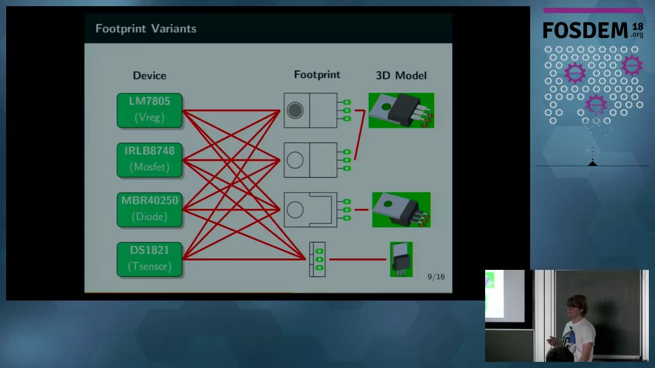
- A multi-tiered library architecture formally decouples abstract components from symbol styles and physical footprint variants, preventing combinatorial explosion across devices and packages. (6:39)
- The platform supports managing multiple independent PCB layouts from a single schematic within one project, keeping connectivity synchronized in real time across different package choices. (14:55)
Detailed notes
## Background Published on YouTube by the FOSDEM channel on February 5, 2018, this presentation features developer Urban Bruhin introducing LibrePCB at FOSDEM 2018. The talk serves as an introduction to LibrePCB, presenting it as a new, powerful, and intuitive open-source EDA tool designed to streamline electronics design for everyone.
## TL;DR Frustrated by the clunky library management, broken version control workflows, and path-configuration mazes of existing tools like KiCad and Eagle, Urban Bruhin built LibrePCB from scratch in C++ and Qt. The suite introduces UUID-based asset tracking, automated dependency resolution, and a clean separation between abstract schematic symbols and physical package variants. Bruhin demonstrates a live workflow featuring real-time schematic-to-PCB synchronization and the ability to maintain multiple distinct board layouts from a single schematic. While core systems like library management and Gerber export are functional, Bruhin outlines the roadmap toward a stable 1.0 release, prioritizing file-format stabilization and board-editor refinement.
## Atmosphere & style The presentation carries the classic, earnest charm of a grassroots open-source conference talk, marked by understated enthusiasm and technical pragmatism. Bruhin speaks with modest, unhurried Swiss precision, candidly acknowledging rough edges, placeholder circuits, and work-in-progress quirks in the board editor without defensiveness. The room feels engaged and technically discerning, resulting in an authentic demo environment where the relief of escaping legacy EDA friction genuinely resonates with the audience.
## Bulletin - [00:04](https://www.youtube.com/watch?v=vu-h5y6tK34&t=4s) Urban Bruhin launched LibrePCB, an open-source EDA suite built from scratch in C++11 and Qt 5 for Linux, Windows, and macOS, targeting major workflow and library pain points found in legacy tools. - [04:13](https://www.youtube.com/watch?v=vu-h5y6tK34&t=253s) LibrePCB replaces name-based references with permanent UUIDs across all entities (symbols, packages, pins, and pads), preventing broken links and enabling built-in automated dependency resolution. - [06:39](https://www.youtube.com/watch?v=vu-h5y6tK34&t=399s) A multi-tiered library architecture formally decouples abstract components from symbol styles and physical footprint variants, preventing combinatorial explosion across devices and packages. - [14:55](https://www.youtube.com/watch?v=vu-h5y6tK34&t=895s) The platform supports managing multiple independent PCB layouts from a single schematic within one project, keeping connectivity synchronized in real time across different package choices.
## Key takeaways - [00:04](https://www.youtube.com/watch?v=vu-h5y6tK34&t=4s) LibrePCB was created from scratch due to deep frustration with legacy EDA tools suffering from poor library management, clunky interfaces, and Git-unfriendly file formats. - [02:06](https://www.youtube.com/watch?v=vu-h5y6tK34&t=126s) Traditional EDA suites like KiCad and Eagle burden users with complex directory paths, environment variables, and manual dependency tracking. - [04:13](https://www.youtube.com/watch?v=vu-h5y6tK34&t=253s) All library elements—including symbols, packages, pins, and pads—use persistent UUIDs so display names can change without breaking project references. - [04:13](https://www.youtube.com/watch?v=vu-h5y6tK34&t=253s) LibrePCB features an integrated library manager with automated dependency resolution that downloads required upstream libraries seamlessly in the background. - [06:39](https://www.youtube.com/watch?v=vu-h5y6tK34&t=399s) Separating abstract components from symbol variants allows designers to switch between European (IEC) and American (IEEE) conventions without duplicating device data. - [06:39](https://www.youtube.com/watch?v=vu-h5y6tK34&t=399s) A dedicated package layer decouples logical pad mappings from physical footprint variants, avoiding combinatorial explosion across device variants. - [10:20](https://www.youtube.com/watch?v=vu-h5y6tK34&t=620s) Project data is split across fine-grained, human-readable S-expression files (.lp) with auto-generated .gitignore files to isolate design changes from transient GUI state. - [12:54](https://www.youtube.com/watch?v=vu-h5y6tK34&t=774s) At the time of presentation, core library and schematic systems were functional, while the board editor remained in active development lacking DRC and copper planes. - [14:55](https://www.youtube.com/watch?v=vu-h5y6tK34&t=895s) Designers can place abstract schematic components first and defer choosing concrete physical packages or footprint variants until layout. - [14:55](https://www.youtube.com/watch?v=vu-h5y6tK34&t=895s) A single schematic can drive multiple independent board layouts simultaneously, maintaining real-time netlist synchronization across all variants. - [17:57](https://www.youtube.com/watch?v=vu-h5y6tK34&t=1077s) A working Gerber generation engine is built directly into LibrePCB, allowing end-to-end output verifiable in tools like Gerbv. - [18:48](https://www.youtube.com/watch?v=vu-h5y6tK34&t=1128s) The primary development roadmap priorities are finalizing the file format specification against breaking changes and improving board editor ergonomics. - [20:07](https://www.youtube.com/watch?v=vu-h5y6tK34&t=1207s) Retrofitting a fundamentally decoupled, UUID-based library architecture onto legacy codebases like KiCad was considered impractical, justifying a clean-slate implementation. - [20:07](https://www.youtube.com/watch?v=vu-h5y6tK34&t=1207s) Manufacturer part numbers and distributor order codes are planned additions for the library system, while panelization and multi-view layouts remain future release goals.
## Detailed walkthrough ### [00:04](https://www.youtube.com/watch?v=vu-h5y6tK34&t=4s) Origins and Motivation for a New EDA Tool
Urban Bruhin, a developer from Switzerland, introduces LibrePCB as a new, open-source EDA (Electronic Design Automation) tool suite built to provide a modern, intuitive electronics design workflow. LibrePCB is fully multi-platform, running on Linux, Windows, and macOS, and has been developed from scratch in C++ using the Qt framework. Bruhin kicked off the project around five years prior (circa 2013), hosting the source code publicly on GitHub.
The initial impulse to build an entirely new tool stemmed from profound frustration with the existing open-source and proprietary electronics software landscape at the time. Reflecting on the state of tools like KiCad half a decade earlier, Bruhin found that existing software suffered from fundamentally broken workflows. The most severe pain points centered on inflexible library architectures, awkward user interfaces, and file formats that actively resisted version control systems like Git—either because they relied on opaque binary blobs or generated messy, unmergeable text files.
- **Technology Stack:** Written from scratch in C++ and Qt - **Supported Platforms:** Linux, Windows, macOS - **Project Age:** In active development since roughly 2013 - **Repository:** Hosted as open source on GitHub
---
[02:06](https://www.youtube.com/watch?v=vu-h5y6tK34&t=126s) The Pain of Existing Library Management
Examining existing EDA software reveals deep structural flaws in how component libraries are stored, shared, and configured. Many legacy tools force different file formats onto different types of library assets—one format for schematic symbols, another for PCB footprints, and potentially yet another if SPICE simulation models are introduced later. Furthermore, existing suites routinely offload the burden of library maintenance onto the end user. They lack integrated package managers, leaving engineers to manually track down zip files from vendor websites, place them in arbitrary directories, and resolve component dependencies by hand.
Bruhin illustrates this cognitive overload by highlighting the configuration panels in Eagle and KiCad. In KiCad's footprint and schematic library managers, users are greeted by dense grids of hardcoded absolute paths, environment variables, path substitution aliases, and confusing distinctions between project-specific and global library tables. When an engineer simply wants to place a part, navigating this maze of file paths creates needless friction.
As Urban Bruhin summarizes his reaction to these traditional workflows: “I asked myself why so complicated I just want to use these libraries so my answer is it doesn't have to be that complicated.”
---
[04:13](https://www.youtube.com/watch?v=vu-h5y6tK34&t=253s) UUID-Based References and Automated Dependencies
LibrePCB addresses these library shortcomings by integrating a built-in library manager directly into the application, complete with an automated dependency resolution engine. When a user chooses to install a library that relies on upstream symbols or components, LibrePCB fetches and configures all required dependencies automatically in the background.
```mermaid flowchart TD accTitle: LibrePCB Architecture accDescr: Diagram showing how UUID-based references eliminate broken links across decoupled library entities.
subgraph LibraryA["Library A"] CMP["Component UUID"] end
subgraph LibraryB["Library B"] SYM["Symbol UUID"] PIN["Pin UUIDs"] end
subgraph LibraryC["Library C"] PKG["Package UUID"] PAD["Pad UUIDs"] end
CMP -->|"persistent reference"| SYM CMP -->|"persistent reference"| PKG SYM --- PIN PKG --- PAD ```
A core architectural flaw in legacy tools is referencing items across libraries strictly by human-readable names, which causes broken references whenever an item is renamed, triggers name collisions, and prevents parts in one library from cleanly sharing assets with another. LibrePCB instead assigns permanent Universally Unique Identifiers (UUIDs) to every individual entity in the library system—including symbols, components, packages, pins, and pads.
Because entity identities are decoupled from their display labels, users can rename symbols or pins at will without breaking downstream projects. This UUID scheme is expressed cleanly within LibrePCB's S-expression (`.lp`) file format, where the unique identifier acts as the primary key and the display name is merely an editable metadata attribute.
As Urban Bruhin emphasizes regarding this seamless setup: “probably the the most important thing is the application basically handles everything for you so you don't have to care about libraries they just work so because there is no reason to make this very complicated”.
---
[06:39](https://www.youtube.com/watch?v=vu-h5y6tK34&t=399s) Decoupling Symbols and Packages: Variants vs. Combinatorial Explosion
Conventional tools often lack the semantic hierarchy needed to represent real-world electronic components cleanly. For instance, a basic resistor may need an IEEE/American zigzag symbol or an IEC/European rectangular symbol. In software like Eagle, achieving this requires creating entirely separate component entries for each visual style, which then forces the designer to duplicate every associated device mapping and package footprint across each component clone.
LibrePCB solves this duplication crisis by introducing a formal separation between the abstract **Component** and its **Symbol Variants**. There is only one central resistor component in the database, but it can hold multiple interchangeable graphical representations (such as European and American styles) without replicating any device metadata.
```mermaid flowchart LR accTitle: Device and Package Abstraction accDescr: Flowchart illustrating how LibrePCB avoids many-to-many relationship explosions between devices and footprint variants.
subgraph Devices["Devices"] D1["Device 1 (e.g. LM7805)"] D2["Device 2 (e.g. LM317)"] end
subgraph PackageEntity["Package Abstraction"] PKG["Package: TO-220 (Defines Pad UUIDs)"] end
subgraph Footprints["Footprint Variants"] FP1["Vertical / Standard"] FP2["Horizontal / Flat"] FP3["Hand-soldering Pads"] end
D1 --> PKG D2 --> PKG PKG --> FP1 PKG --> FP2 PKG --> FP3 ```
A parallel issue plagues physical footprints. Physical components such as a TO-220 voltage regulator frequently require multiple footprint variations—for vertical mounting, horizontal mounting, or oversized pads designed specifically for hand-soldering rather than reflow ovens. Without an intermediate abstraction layer, every single device variant must maintain an explicit link to every single physical footprint variant, triggering an unmanageable $N \times M$ combinatorial explosion of relationships.
LibrePCB resolves this by inserting a dedicated **Package** entity. The package defines the logical pad layout and pin assignments, allowing devices to link solely to the package. The package itself then encapsulates as many alternative footprint implementations as needed.
---
[10:20](https://www.youtube.com/watch?v=vu-h5y6tK34&t=620s) Designing File Formats for Human Readability and Git
Version-controlling board designs is notoriously painful in existing EDA suites because files routinely mix essential design data with volatile UI state. Checking in a PCB often produces massive diffs containing local changes even when no traces or schematics were modified. Bruhin demonstrates this by showing a diff from a KiCad board file where simply panning, zooming, and toggling visibility layers altered internal view state and flipped individual floating-point bits, creating false modifications.
LibrePCB counters this by distributing project data across multiple smaller, specialized files rather than dumping an entire design into one monolithic file. This high granularity makes it straightforward to distinguish critical board changes from transient editor state. To prevent common tracking mistakes, LibrePCB automatically initializes a suitable `.gitignore` file inside every newly created project directory.
Beyond splitting files, Bruhin stresses that text-based storage does not automatically equal human readability: “not every text-based file format is human readable you you need to control every tiny detail of the file format to me to make it as readable as possible and in LibrePCB I consider parts of files which are not really human readable as bugs and bugs need to be fixed”.
---
[12:54](https://www.youtube.com/watch?v=vu-h5y6tK34&t=774s) Development Status and Live Demonstration
Reviewing the software's readiness, Bruhin explains that while foundational subsystems are solid, LibrePCB is still early in its journey toward a 1.0 release:
- **Library Management:** Highly functional with automatic dependency resolution. - **Library Editor:** Functional for basic creation tasks, but still limited in scope. - **Schematic Editor:** Stable and usable for basic schematics, though missing convenience features like copy-and-paste. - **Board Editor:** Actively under heavy development; lacking copper planes, airwires (ratsnest), and a Design Rule Check (DRC), though basic Gerber export already works. - **Stability Warning:** The on-disk file format is not yet finalized or guaranteed to be forward-compatible across future releases.
Bruhin runs a live demonstration using an official standalone Linux AppImage downloaded directly from the web. Launching it for the first time, the application prompts the user to establish a workspace directory. Upon opening the main control panel, the interface alerts the user that no libraries are currently installed. Opening the built-in Library Manager presents an online repository catalog. Selecting a desired component library automatically marks and installs its required upstream dependencies, confirming that the automated package management functions out of the box without requiring manual file manipulation.
[14:55](https://www.youtube.com/watch?v=vu-h5y6tK34&t=895s) Live Demo: Schematics, Multi-Board Layouts, and Real-Time Sync
Urban Bruhin walks through a live demonstration of LibrePCB, starting by opening some downloaded libraries and creating a brand new project. Moving into the schematic editor, he places a few sample components to demonstrate how intuitive the workflow is. He highlights the flexibility of the library system right away: for basic parts like capacitors, users can seamlessly choose between European and American schematic symbols. Furthermore, designers do not have to commit to physical packages upfront; they can place an abstract component—such as a generic n-channel MOSFET without assigning a footprint—or select an exact device immediately. He wires up a simple circuit with a resistor, transistor, and ground, admitting with a chuckle that the dummy circuit “doesn't make sense,” but serves to illustrate the process.
```mermaid flowchart TD accTitle: LibrePCB Schematic and Multi-Board Workflow accDescr: Diagram showing how a single schematic feeds multiple independent board layouts in LibrePCB.
subgraph Schematic["Schematic Editor"] SCH["Schematic Circuit<br/>(Generic or Exact Components)"] end
subgraph Boards["Board Editor Options"] B1["Board Layout 1<br/>(e.g., SMD Variant)"] B2["Board Layout 2<br/>(e.g., TO-220 Through-Hole)"] end
SCH -->|"Synchronized in Real Time"| B1 SCH -->|"Synchronized in Real Time"| B2 ```
Switching over to the board editor, LibrePCB displays a dock listing unplaced parts that are missing from the PCB layout. Bruhin assigns specific packages and packages devices on the fly, picking a resistor and choosing from two available device options for the MOSFET. For the TO-220 package, he demonstrates selecting between different mounting variants (such as vertical or bent horizontal mounting). He then reveals a standout feature: users can duplicate a board layout to maintain multiple independent PCB designs within the same project. One board can use surface-mount devices while the duplicate can use alternative through-hole footprints or different mounting orientations. Despite these independent packaging choices, the underlying connectivity remains strictly synchronized with the schematic. As Bruhin observes, “And also the important the schematic is also in think is always in sync so for example if I remove on the resistor it disappears from both ports in the time yeah yeah it's so it's like an eagle basically.”
- **Symbol flexibility:** Supports switching between American and European schematic symbols at placement time. - **Packaging decoupling:** Designers can place logical symbols first and defer choosing footprints or packaging variants until layout. - **Multiple boards per project:** Projects can hold more than one board design side by side, allowing different form factors or mounting variants for the same schematic. - **Live synchronization:** Deleting or altering parts in the schematic instantly propagates across all corresponding boards in the project.
[17:57](https://www.youtube.com/watch?v=vu-h5y6tK34&t=1077s) Board Editor Status and Gerber Export
Bruhin encounters a minor hiccup when attempting to delete a part directly from the board layout, taking the opportunity to remind the audience about the software's development status. He explains that deleting a component from a board removes its placement rather than deleting the electrical symbol, returning it to the list of unplaced board items while leaving it untouched on any alternative board layouts. He candidly acknowledges that the layout workspace is still an active work in progress: “I say it already the board editor is in working progress so there are some yeah strange things.”
To prove that the pipeline is already functional end-to-end, Bruhin shows off the built-in Gerber exporter. Even though it is currently a bare-bones implementation lacking detailed customization dialogs, it functions reliably with a single click. He presses generate, opens the output directory, and invites the audience to verify the result: “And if you didn't don't trust me the files are generated in this so yeah so you can just open them we care for you for example and here it is so very simple but it works.” He opens the exported files in Gerbv, displaying the rendered PCB layers on screen.
[18:48](https://www.youtube.com/watch?v=vu-h5y6tK34&t=1128s) Development Roadmap and Tech Stack
Looking ahead, Bruhin details the immediate milestones required before LibrePCB can reach general readiness. The team's top focus is finalizing and stabilizing the underlying file format to ensure that users do not experience breaking changes after release. Following that, polishing the board editor into a comfortable, mature tool is essential, as Bruhin admits that using the current incomplete editor “doesn't make fun like that,” even though it is technically mature enough to produce Gerber files and order physical PCBs. He invites community members to join the effort before opening the floor to questions: “The first the highest priority at the moment is to stabilize the file format so to the loss breaking changes and to create the first stable release.”
In response to the first audience question regarding the implementation details, Bruhin explains that LibrePCB is engineered in modern C++11 and utilizes the Qt 5 framework for its cross-platform graphical user interface and core libraries.
- **Primary milestone:** Finalize the file format specification and eliminate breaking schema changes. - **Secondary milestone:** Enhance board layout ergonomics, routing tools, and editing features to deliver an enjoyable user experience. - **Implementation stack:** Built using modern C++11 and Qt 5. - **Community call:** Welcomes outside contributors and developers to accelerate core feature development.
[20:07](https://www.youtube.com/watch?v=vu-h5y6tK34&t=1207s) Q&A: Architectural Differences with KiCad, Part Numbers, and Views
An audience member asks why Bruhin decided to build a brand new EDA tool from scratch rather than contributing his efforts to existing open-source projects like KiCad. Bruhin explains that his reasoning mirrors the rationale given by the Horizon EDA project: EDA software is fundamentally constrained by its library architecture, and retrofitting a fundamentally different library paradigm onto an established codebase is virtually impossible. Addressing this deep structural divide, Bruhin explains: “Because I think the library system is that important part of over EDI tool and it's it's a very fundamental low-level part and it's very hard to change this concept and I think in liebherr PCB the concept is completely different than in kicad.”
```mermaid flowchart LR accTitle: KiCad vs LibrePCB Library Design Philosophy accDescr: Flow comparison showing KiCad's symbol-footprint mapping compared to LibrePCB's multi-layered semantic component model.
subgraph KiCad["KiCad Traditional Approach"] direction TB KSYM["Schematic Symbol"] -->|"Direct association / netlist mapping"| KFP["PCB Footprint"] end
subgraph LibrePCB["LibrePCB Structured Approach"] direction TB LSYM["Abstract Component / Symbol"] --> LDEV["Device Model"] LPKG["Package & Footprint Options"] --> LDEV LDEV -->|"Integrated Parts & Assembly Variants"| LBRD["Board Layouts"] end ```
The Q&A continues with audience questions regarding component sourcing and multi-panel board visualization:
- **Order codes and manufacturer part numbers:** When asked whether distributor order numbers and exact manufacturer part numbers are embedded inside the library system, Bruhin clarifies that they are not included yet. However, he emphasizes that clear plans are already in place to integrate ordering codes and part numbers directly into the library architecture in a future update. - **Multiple board views and panels:** An attendee asks whether LibrePCB intends to support having multiple synchronized views of the same board (such as viewing specific sub-regions or setting up multi-board panelization). Bruhin responds that although it is not currently planned for the initial release, having multi-view board support would certainly be a valuable addition down the line.
## Notable quotes > [10:20](https://www.youtube.com/watch?v=vu-h5y6tK34&t=620s) in LibrePCB I consider parts of files which are not really human readable as bugs and bugs need to be fixed — Urban Bruhin
## Mentioned Urban Bruhin, LibrePCB, FOSDEM, KiCad, Eagle, Horizon EDA, Git, GitHub, C++, Qt, Linux, Windows, macOS, AppImage, Gerbv, SPICE
## Video description by Urban Bruhin
At: FOSDEM 2018 Room: K.4.201 Scheduled start: 2018-02-03 16:00:00+01
[Source](https://www.youtube.com/watch?v=vu-h5y6tK34)