Ben Eater Rebuilds 8-Bit Breadboard Computer on Camera from Scratch
Ben Eater
Anyone can understand computer architecture at a fundamental level without prior electronics training by methodically assembling hardware modules and debugging circuits from first principles.
AI-assisted summary of 8-bit computer update — original source. Check the original for full context.
Source published:
Key ideas
- Ben Eater announced a complete rebuild of his breadboard 8-bit computer from scratch on camera, teaching every concept from first principles without formal prior schematics. (3:24)
- The computer is grounded in Albert Paul Malvino's SAP-1 architecture from 'Digital Computer Electronics', expanded with 16 bytes of RAM, a decimal display, and added instructions like store and conditional jumps. (0:53)
- The tutorial series aims for a cadence of at least one video per week, starting with a 555-timer-based clock module featuring variable speed and manual stepping. (4:02)
Detailed notes
## Background Published on YouTube by Ben Eater on March 9, 2016, this video provides an update on his plans to build another 8-bit breadboard computer from scratch and document the entire process on camera. The description highlights kit availability for viewers who want to build along at home and links to his Patreon page.
## TL;DR Addressing frequent viewer requests for schematics, Ben Eater explains that his 8-bit breadboard computer was built modularly without a formal blueprint, adapting Albert Paul Malvino's SAP-1 architecture with custom upgrades such as a decimal display and extra instructions. To properly document the build, Eater announces a comprehensive reconstruction series where he will assemble another computer from scratch, teaching digital logic from first principles at a pace of roughly one video per week. He reassures viewers that anyone can succeed with patience and systematic debugging, before previewing the first project: a flexible 555-timer-based master clock with adjustable speeds and manual single-stepping.
## Atmosphere & style The presentation is calm, earnest, and encouraging, marked by Ben's transparent admission that his sprawling breadboard masterpiece never had a formal master schematic. His pedagogical style is grounded and accessible, stripping away intimidating academic pretense to frame complex digital electronics as an approachable, step-by-step craft. The experience feels like an inviting open-door invitation into an engineer's workbench, pairing patient explanations with the satisfying tactile click of switches and slowing clock pulses.
## Bulletin - [03:24](https://www.youtube.com/watch?v=HyznrdDSSGM&t=204s) Ben Eater announced a complete rebuild of his breadboard 8-bit computer from scratch on camera, teaching every concept from first principles without formal prior schematics. - [00:53](https://www.youtube.com/watch?v=HyznrdDSSGM&t=53s) The computer is grounded in Albert Paul Malvino's SAP-1 architecture from 'Digital Computer Electronics', expanded with 16 bytes of RAM, a decimal display, and added instructions like store and conditional jumps. - [04:02](https://www.youtube.com/watch?v=HyznrdDSSGM&t=242s) The tutorial series aims for a cadence of at least one video per week, starting with a 555-timer-based clock module featuring variable speed and manual stepping.
## Key takeaways - [00:16](https://www.youtube.com/watch?v=HyznrdDSSGM&t=16s) The original breadboard computer was built modularly without a complete master schematic drawn beforehand. - [00:53](https://www.youtube.com/watch?v=HyznrdDSSGM&t=53s) The design adapts the SAP-1 ('Simple As Possible-1') architecture from Albert Paul Malvino's textbook 'Digital Computer Electronics'. - [01:19](https://www.youtube.com/watch?v=HyznrdDSSGM&t=79s) The machine utilizes 16 bytes of RAM instead of the programmable read-only memory described in the original SAP-1 design. - [01:50](https://www.youtube.com/watch?v=HyznrdDSSGM&t=110s) The stock SAP-1 instruction set of five commands was expanded to include immediate load, store (STA), unconditional jump, and conditional jump on carry. - [01:45](https://www.youtube.com/watch?v=HyznrdDSSGM&t=105s) Hardware upgrades beyond the baseline SAP-1 include a decimal output readout replacing the raw binary display. - [01:33](https://www.youtube.com/watch?v=HyznrdDSSGM&t=93s) Yellow wiring across the breadboards routes control signals dispatched by the control unit to synchronize all modules. - [03:24](https://www.youtube.com/watch?v=HyznrdDSSGM&t=204s) The upcoming video series will reconstruct the entire machine completely from scratch, emphasizing first-principles explanations. - [03:56](https://www.youtube.com/watch?v=HyznrdDSSGM&t=236s) Completing the reconstruction series is projected to take at least several months, targeting a release pace of one video per week. - [04:17](https://www.youtube.com/watch?v=HyznrdDSSGM&t=257s) Building the computer requires no formal electronics background, relying primarily on neat wiring and systematic debugging. - [05:06](https://www.youtube.com/watch?v=HyznrdDSSGM&t=306s) The first module to be constructed is the master clock circuit built around 555 timer integrated circuits. - [05:31](https://www.youtube.com/watch?v=HyznrdDSSGM&t=331s) The master clock integrates potentiometer-driven variable speed control alongside a halt mode and a manual single-step button for debugging.
## Detailed walkthrough ### [00:00](https://www.youtube.com/watch?v=HyznrdDSSGM&t=0s) Building Without Schematics: The SAP-1 Model and Custom Enhancements
Ever since Ben Eater uploaded videos of his breadboard-based 8-bit programmable computer, viewers have repeatedly asked for schematics or a step-by-step tutorial. Ben confesses that he never actually drafted a complete schematic before assembling the machine. Because the design is fundamentally modular, he was able to build, test, and experiment with one distinct module at a time before integrating them. He explains that it was only when bringing all the sections together that he had to be more deliberate about the full system's operation.
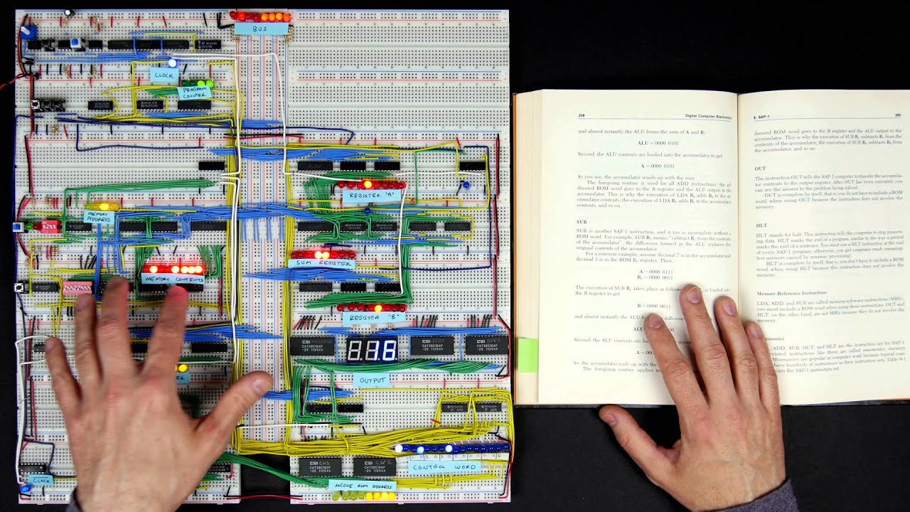
For the foundational blueprint, Eater followed the architecture presented in the textbook *Digital Computer Electronics* by Albert Paul Malvino. Though out of print, he strongly recommends seeking out a used copy. The book introduces simplified architectures, most notably the SAP-1 ("Simple As Possible-1"), designed to demonstrate the core principles of computer operations without unnecessary complexity. Eater’s computer incorporates all the primary elements of the SAP-1: a program counter, a memory address register (MAR), 16 bytes of memory (RAM in Eater's build, where Malvino used programmable read-only memory), an instruction register, a control unit, an accumulator (A register), a B register, an arithmetic logic unit (ALU) limited strictly to addition and subtraction, and an output display. The sprawling mass of yellow wires running across the breadboards carries control signals dispatched from the control unit to orchestrate the entire machine.
Eater also added several hardware and instruction set enhancements over the book's baseline design. Where Malvino's SAP-1 featured a binary output, Eater incorporated a decimal display. In terms of software capabilities, the textbook only provided five instructions: load accumulator (`LDA`), add (`ADD`), subtract (`SUB`), output (`OUT`), and halt (`HLT`). Eater extended this by adding an immediate load command to save memory, a store instruction (`STA`) to write the accumulator back into RAM, an unconditional jump, and a conditional jump that triggers on an addition overflow carry bit. Regarding his lack of formal blueprints, Ben admits: “The answer is, believe it or not, I actually don't have schematics for this thing, I never sat down and drew out a full schematic.”
```mermaid flowchart TD accTitle: SAP-1 Architecture with Eater Enhancements accDescr: High-level overview of the 8-bit computer architecture based on SAP-1 and modified by Ben Eater.
subgraph MemoryControl ["Control & Addressing"] PC["Program Counter"] MAR["Memory Address Register"] RAM["16 Bytes RAM"] IR["Instruction Register"] CU["Control Unit\n(Yellow Signal Wires)"] end
subgraph Datapath ["ALU & Registers"] RegA["Accumulator (A Register)"] RegB["B Register"] ALU["ALU\n(Add & Subtract)"] end
subgraph OutputSection ["Output & Peripherals"] OutReg["Output Register"] Disp["Decimal Display\n(Enhancement)"] end
PC --> MAR MAR --> RAM RAM --> IR IR --> CU CU -.->|"Control Signals"| PC CU -.->|"Control Signals"| RAM CU -.->|"Control Signals"| RegA CU -.->|"Control Signals"| ALU CU -.->|"Control Signals"| OutReg
RAM <--> RegA RegA --> ALU RegB --> ALU ALU --> RegA RegA --> OutReg OutReg --> Disp ```
- **Reference material:** *Digital Computer Electronics* by Albert Paul Malvino (SAP-1 architecture). - **Core memory size:** 16 bytes. - **Stock SAP-1 instructions:** Load A (`LDA`), Add (`ADD`), Subtract (`SUB`), Output (`OUT`), Halt (`HLT`). - **Eater's instruction set additions:** Load immediate, Store A (`STA`), Unconditional Jump (`JMP`), Conditional Jump on Carry (`JC`). - **Display upgrade:** Converted Malvino's raw binary output display into a decimal readout.
---
[03:24](https://www.youtube.com/watch?v=HyznrdDSSGM&t=204s) The Reconstruction Series Plan and First Principles
To address the requests for guides and schematics, Ben announces a project to reconstruct an entire copy of the computer completely from scratch on camera. His pedagogical commitment is to teach every single concept from first principles so that viewers are never forced to accept anything blindly. However, because of his limited free time and the methodical pace required to detail every underlying mechanism, the project will require a significant amount of time—at least a few months, and likely longer. He sets a baseline personal goal of releasing at least one video per week.
Ben firmly believes that anyone can successfully replicate this build, regardless of whether they have a background in electronics, provided they possess the patience to wire each lead neatly and the perseverance to debug inevitable errors. “I'm convinced that anyone can build this and really understand at a very deep level, how a computer works, by building this,” Ben states, emphasizing his desire to see viewers build and perhaps even expand upon the system.
- **Production goal:** Publish at least one video per week. - **Project scope:** A complete, breadboard-by-breadboard reconstruction filmed from scratch. - **Teaching philosophy:** Ground every design decision in first principles without relying on unexplained shortcuts. - **Prerequisites:** No prior electronics experience needed; requires only careful wiring habits and systematic debugging.
---
[05:06](https://www.youtube.com/watch?v=HyznrdDSSGM&t=306s) The Next Step: Variable 555-Based Clock Module
The series will begin with the design and construction of the master clock circuit, which coordinates the timing and operational states across all other functional units. Ben notes that he will be traveling over the coming week, meaning the clock video will debut in roughly two weeks.
The clock unit is engineered around 555 timer ICs configured for several distinct operational roles. Rather than remaining locked at a static frequency, the clock features a variable speed potentiometer—which Ben demonstrates by noticeably slowing down the execution speed of the entire machine—as well as a halt switch. Once halted, the user can pulse a manual single-step button, advancing the machine one clock cycle at a time. This manual stepping capability is vital for diagnosing errors, as troubleshooting faulty connections is an unavoidable phase of assembling the computer. Concluding the update, Eater encourages viewers to like, subscribe, and share the project, explaining that community interest and feedback serve as his primary motivation to keep creating the videos.
- **Upcoming build focus:** The master system clock. - **Key active components:** Multiple 555 timer integrated circuits. - **Clock operating modes:** - Adjustable continuous frequency (variable speed control via potentiometer). - Full stop / halt. - Manual single-step pulsing for cycle-by-cycle hardware debugging. - **Release timeframe:** Video launch expected in approximately two weeks following travel.
## Notable quotes > [03:24](https://www.youtube.com/watch?v=HyznrdDSSGM&t=204s) I'm convinced that anyone can build this and really understand at a very deep level, how a computer works, by building this — Ben Eater
## Mentioned Ben Eater, Albert Paul Malvino, Digital Computer Electronics, SAP-1, 555 timer IC, Patreon, YouTube
## Video description An update on my plans to build another 8-bit computer from scratch and make videos of the whole process! Buy a kit and build your own! https://eater.net/8bit/kits
Support me on Patreon: https://www.patreon.com/beneater
[Source](https://www.youtube.com/watch?v=HyznrdDSSGM)